Creating and Using Math Waveforms
CSA7000B Series & TDS7000B Series Instruments User Manual
3- 195
-- 1 0
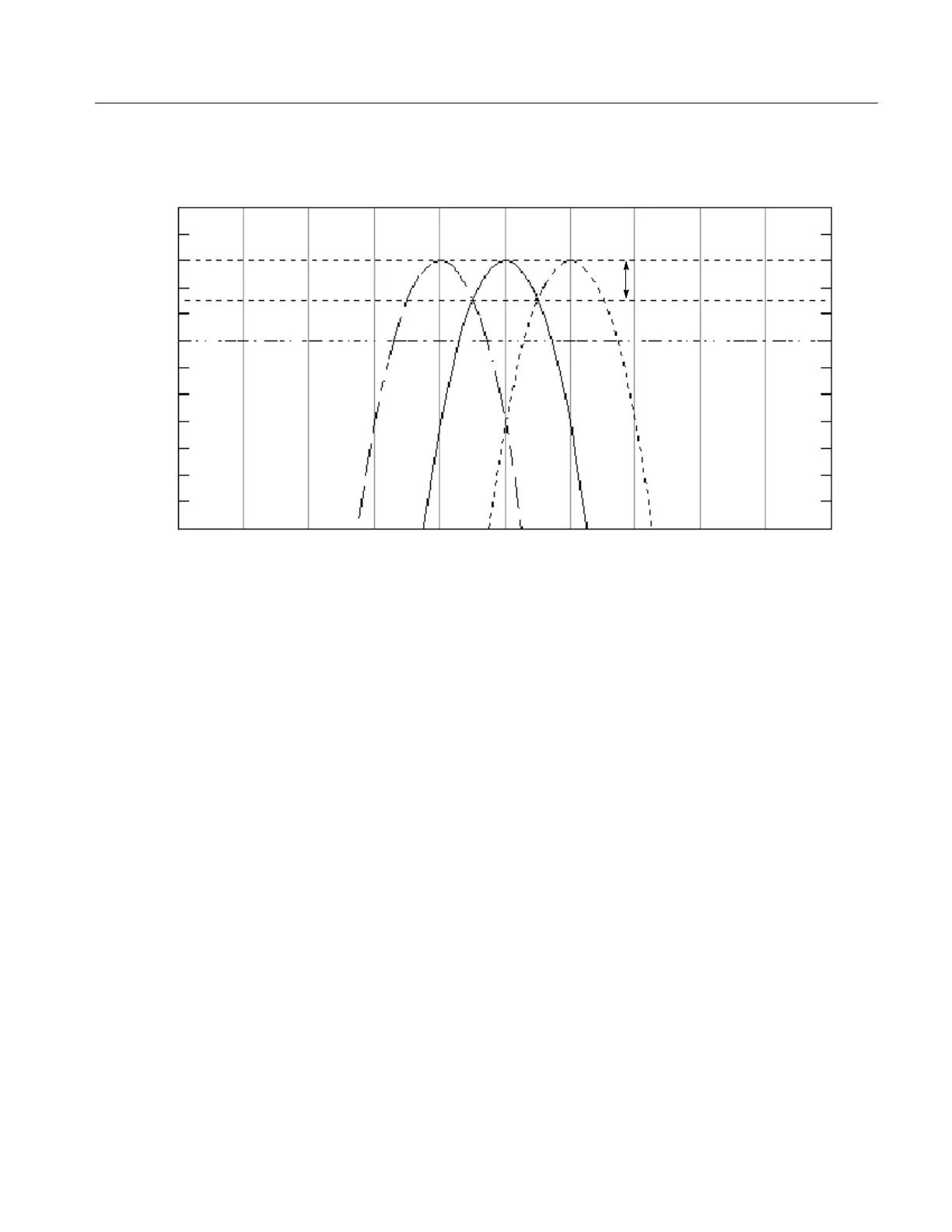
Hanning scallop loss is 1.42 dB
Frequency bins
+2
+1
0
-- 1
-- 2
-- 3
-- 4
-- 5
-- 6
-- 7
-- 8
-- 9
dB
Figure 3- 54: Example of scallop loss for a Hanning window without zero fill
H Nearest Side Lobe. This is the difference in magnitude between the spectral
lobe peak in the spectrum and the next side lobe that occurs due to ener gy
leakage. Different windows have different leakage characteristics. The more
narrow the resolution bandwidth of the window, the more leakage in the
spectrum.
H Zero Phase Reference. This is the position in the time domain gate that is the
reference point for phase in the output spectrum. That is, if a sine wave input
has its peak at the zero phase reference position, then it reads out as zero
phase in the spectrum. If the phase is to be correct when doing impulse
response testing, the impulse in the time domain must be located at this
position in the gate interval.
H Coefficients. These are used to generate the windows which are constructed
from a cosines series. For the Gaussian window the value of “a” is given
instead of a set of coefficients. You can find descriptions of cosine series
windows in Handbook of Digital Signal Processing Engineering Applica-
tions by Elliot. ISBN 0--12--237075--9.