Incoming Inspection
CSA7000B Series & TDS7000B Series Instruments User Manual
1-25
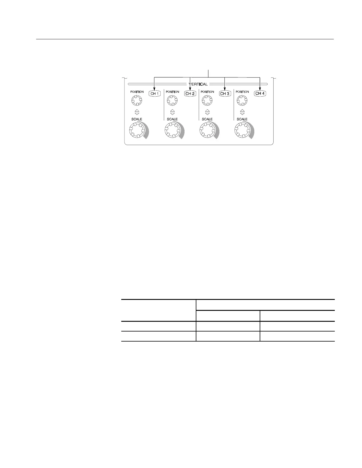
Channel buttons
Figure 1- 10: Channel button location
5. Set up the instrument:
H Push the front-panel AUTOSET button. This sets the horizontal and
vertical scale and vertical offset for a usable display and sets the trigger
source to the channel that you are testing.
H Touch the Vert button and then touch Offset. Confirm that the Ch1
Offset is about --0.18 to --0.54 V (0.0 V if not using a probe).
6. Verify that the channel is operational: Confirm that the following statements
are true.
H Verify that the vertical scale readout and the waveform amplitude for the
channel under test are as shown in Table 1--3.
Table 1- 3: Vertical settings
CSA7404, TDS7704B, TDS7404, TDS7254, & TDS7154
Setting
With P7240 or P7260
Without a probe
Scale 200 mV 200 mV
Waveform amplitude 5.2 divisions 2.5 divisions
H The front-panel vertical POSITION knob (for the channel you are
testing) moves the signal up and down the screen when rotated.
H Turning the vertical SCALE knob counterclockwise (for the channel you
are testing) decreases the amplitude of the waveform on-screen, turning
the knob clockwise increases the amplitude, and returning the knob to
the original scale setting returns the amplitude to that shown in
Table 1--3 for that scale setting.