Incoming Inspection
CSA7000B Series & TDS7000B Series Instruments User Manual
1-29
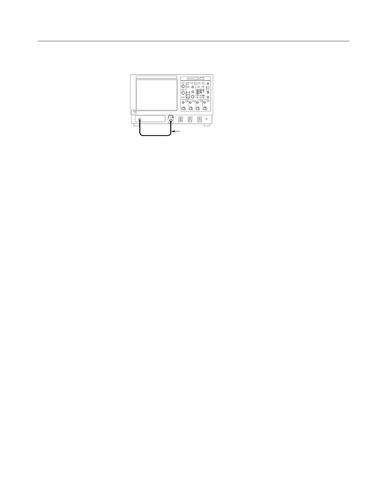
Instrument under test
BNC cable from PROBE
COMPENSATION output
to CH 1 input
Figure 1- 12: Setup for trigger test
4. Touch the Vert button, and then touch Offset. Adjust the Ch1 Offset to
--0.25 V using the multipurpose knob.
5. Set the Vertical SCALE to 100 mV per division.
6. Verify that the main trigger system operates: Confirm that the following
statements are true.
H The trigger level readout for the A (main) trigger system changes with
the trigger-LEVEL knob.
H The trigger-LEVEL knob can trigger and untrigger the square-wave
signal as you rotate it. (Leave the signal untriggered).
H Pushing the front-panel trigger LEVEL knob sets the trigger level to the
50% amplitude point of the signal and triggers the signal that you just
left untriggered. (Leave the signal triggered.)
7. Verify that the delayed trigger system operates:
a. Set up the delayed trigger:
H From the Trig menu, select A→B Sequence . . . . This displays the
A→B Sequence tab of the trigger setup control window.
H Touch the Trig After Time button under A Then B.
H Touch the B T rig Level control in the control window.
b. Confirm that the following statements are true:
H The trigger-level readout for the B trigger system changes as you
turn the lower multipurpose knob.
H As you rotate the lower multipurpose knob, the square-wave
probe-compensation signal can become triggered and untriggered.
(Leave the signal triggered.)