G10 Installation Guide 7.13.2 127
C
Rev. 005-140228
IAP200/IAP320
This section contains the following procedures for the applications blade:
Removing or Resetting the IAP200/IAP320
Installing the IAP200/IAP320
Removing or Resetting the IAP200/IAP320
Perform the following to reset or remove the applications blade.
Step Action
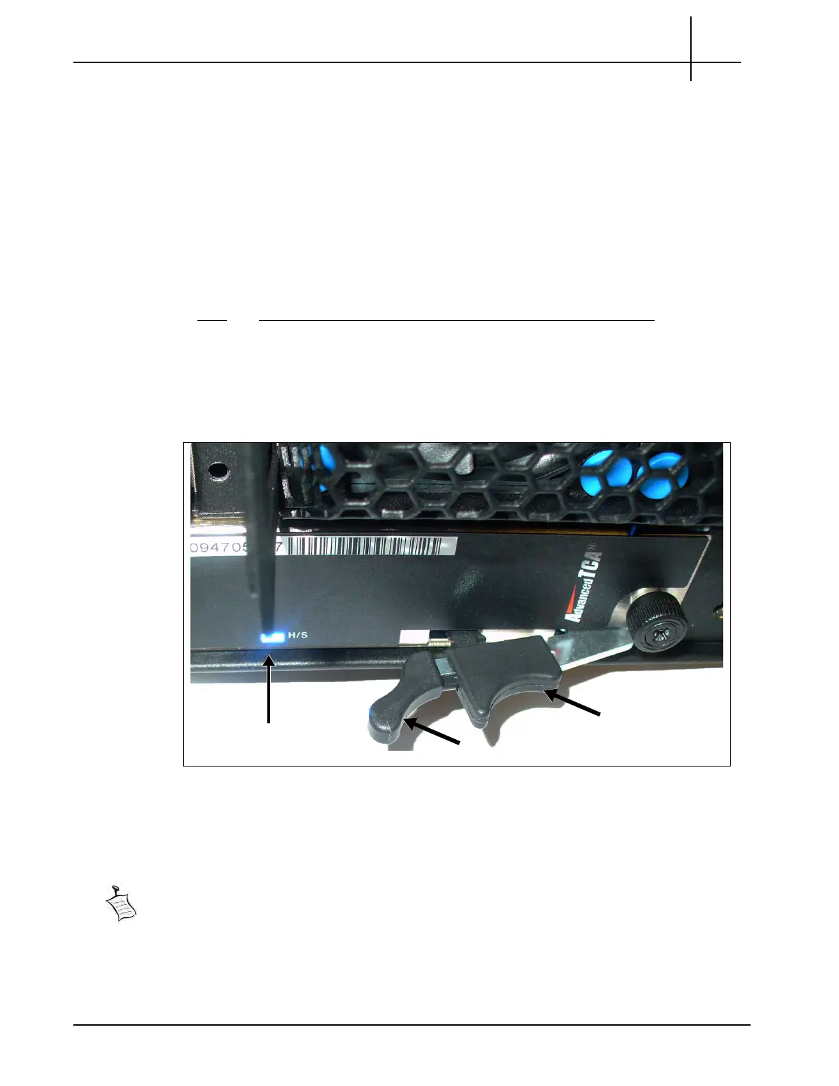
1. Pinch the latch and lever on the right ejector handle and pull the handle outward
slightly as shown (Figure C.19).
2. The blue Hot Swap LED starts to blink, indicating that the blade is shutting down
the OS.
Figure C.19 - IAP Right Ejector Ha
ndle -
Hot Swap Position
3. Wait until the Hot Swap LED is solid blue. Th
is indicates that the blade’s OS has
powered down completely.
If you are resetting the board, pinch the latch and lever together and push the ejector handle
back in toward the chassis until the Hot Swap LED turns off. When the LED turns off, this
indicates that the blade’s payload has been powered up and that the blade is active.
Tektronix Communications | For Licensed Users | Unauthorized Duplication and Distribution Prohibited
 Loading...
