G10 Installation Guide 7.13.2 35
2
Install Hardware and Power Cabling
Rev. 005-140228
INSTALL FUSE PANEL
If a fuse panel is not provided already, the FP100 Fuse Panel must be installed for DC
configurations. Tektronix recommends using the FP100 Fuse Panel or equivalent device for
providing circuit protection for the G10 probe and SAS storage enclosure. Ensure the device is
installed in the same rack as the equipment.
Four-Post Rack, Front Mount
The FP100 fuse panel ships with brackets installed for mid-mount. You must move the
brackets to the front position in order to mount it to the front of the rack.
Step Action
1. Determine the location in the rack in which you will install the fuse panel (see
Example Rack Installations).
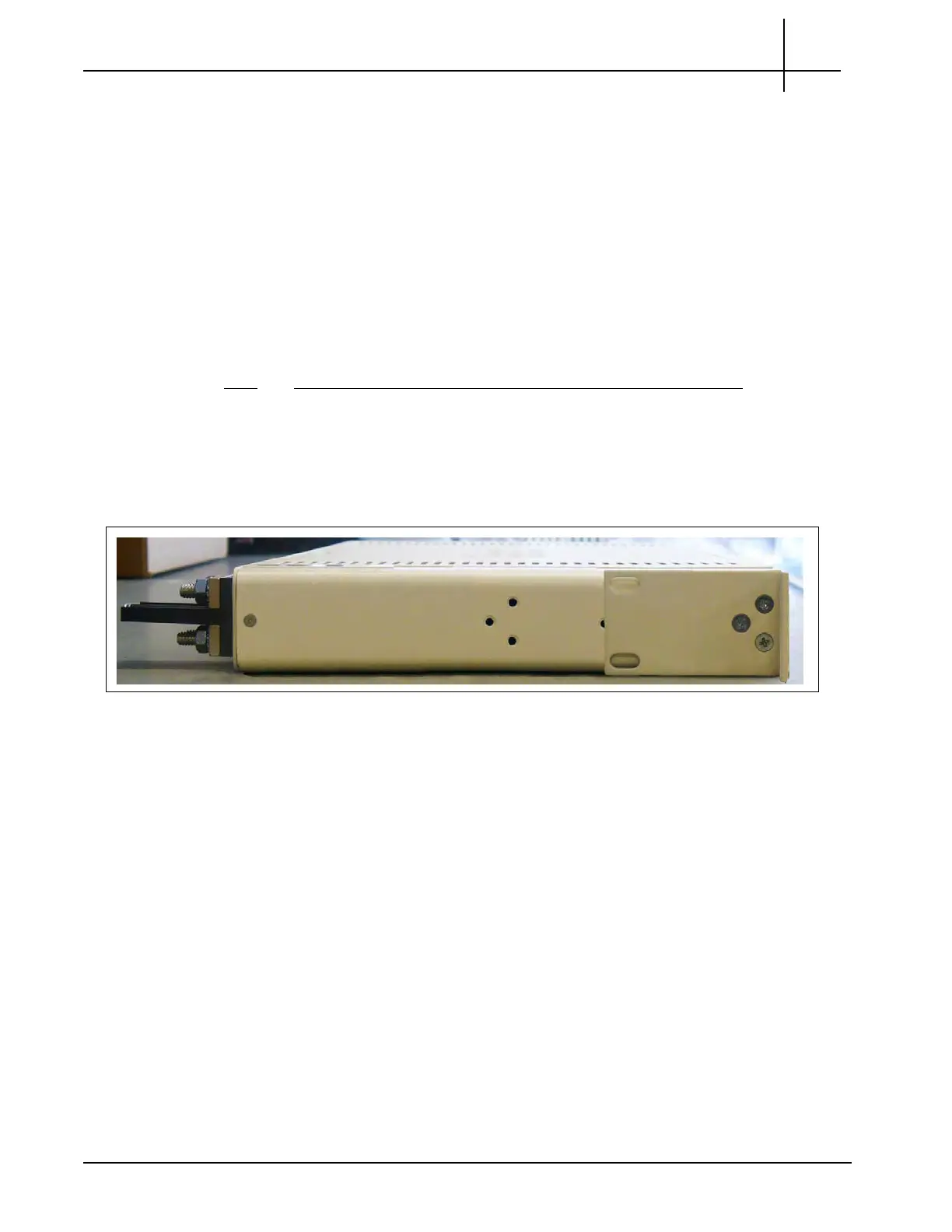
2. Reposition the brackets on each side of the fuse panel to the front mount
po
sition
(Figure 2.19).
Figure 2.19 - Attaching Fuse Panel to Rack Post
Tektronix Communications | For Licensed Users | Unauthorized Duplication and Distribution Prohibited

 Loading...