EasyManuals Logo

Tektronix GeoProbe G10 Installation Guide

Tektronix GeoProbe G10
168 pages
To Next Page IconTo Next Page
To Previous Page IconTo Previous Page
Page #34 background imageLoading...
Page #34 background image
G10 Installation Guide 7.13.2 34
2
Install Hardware and Power Cabling
Rev. 005-140228
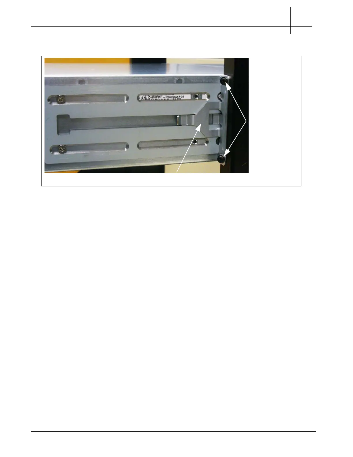
5. Slide the rear brackets into place to align with the post’s mounting holes
(Figure 2.18). Secure the rear bracket to the post with two ra
ckmount screws.
Figure 2.18 - Attaching Rear Bracket to Rack Post
6. For DC configurations, continue with Install Fuse Panel.
For AC configurations, continue with Connect Power Cabling.
Rackmount
Screws
Rear Bracket
Tektronix Communications | For Licensed Users | Unauthorized Duplication and Distribution Prohibited

Table of Contents

Other manuals for Tektronix GeoProbe G10

Questions and Answers:

Question and Answer IconNeed help?

Do you have a question about the Tektronix GeoProbe G10 and is the answer not in the manual?

Tektronix GeoProbe G10 Specifications

General IconGeneral
BrandTektronix
ModelGeoProbe G10
CategoryAccessories
LanguageEnglish