G10 Installation Guide 7.13.2 36
2
Install Hardware and Power Cabling
Rev. 005-140228
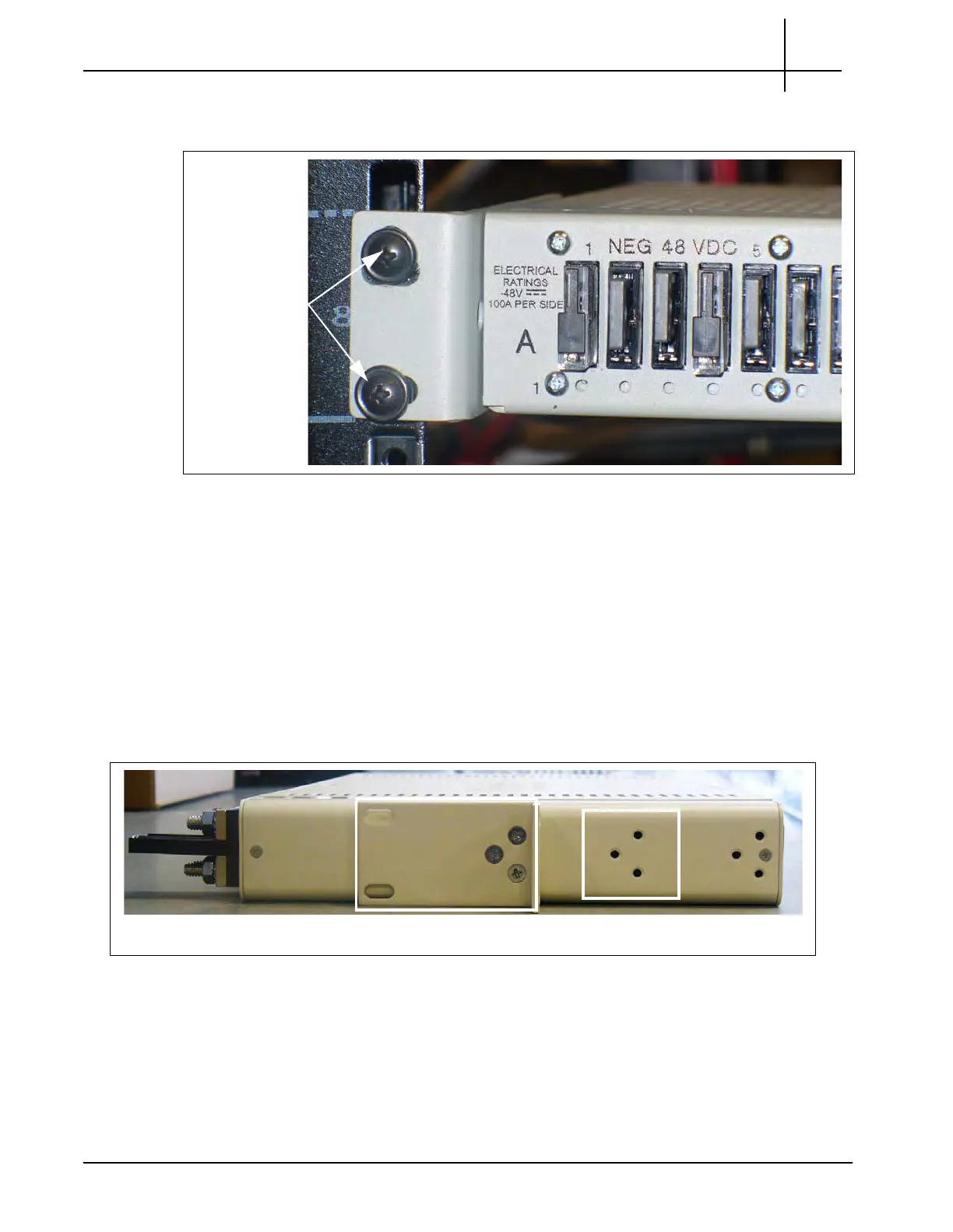
3. Attach the fuse panel to the front of the rack with two rackmount screws on each
side (Figure 2.20).
Figure 2.20 - Attaching Fuse Panel to Rack Post
4. Continue with Connect Power Cabling on
page 38.
Two-Post Rack, Mid Mount
The FP100 fuse panel ships with brackets installed for mid-mount (Figure 2.21) on a 19-inch
wide rack. Screw holes for an alternate mid-mount option are
also available. If installing in a
23-inch wide rack, remove the side brackets and reattach the short sides of the brackets to the
fuse panel to accommodate the 23-inch racks.
Figure 2.21 - Fuse Panel Bracket
Alternate Mid-Mount OptionDefault Mid-Mount Option
Tektronix Communications | For Licensed Users | Unauthorized Duplication and Distribution Prohibited

 Loading...