G10 Installation Guide 7.13.2 149
C
Rev. 005-140228
Installing the Power Supply
To install a power supply module, perform the following steps:
Step Action
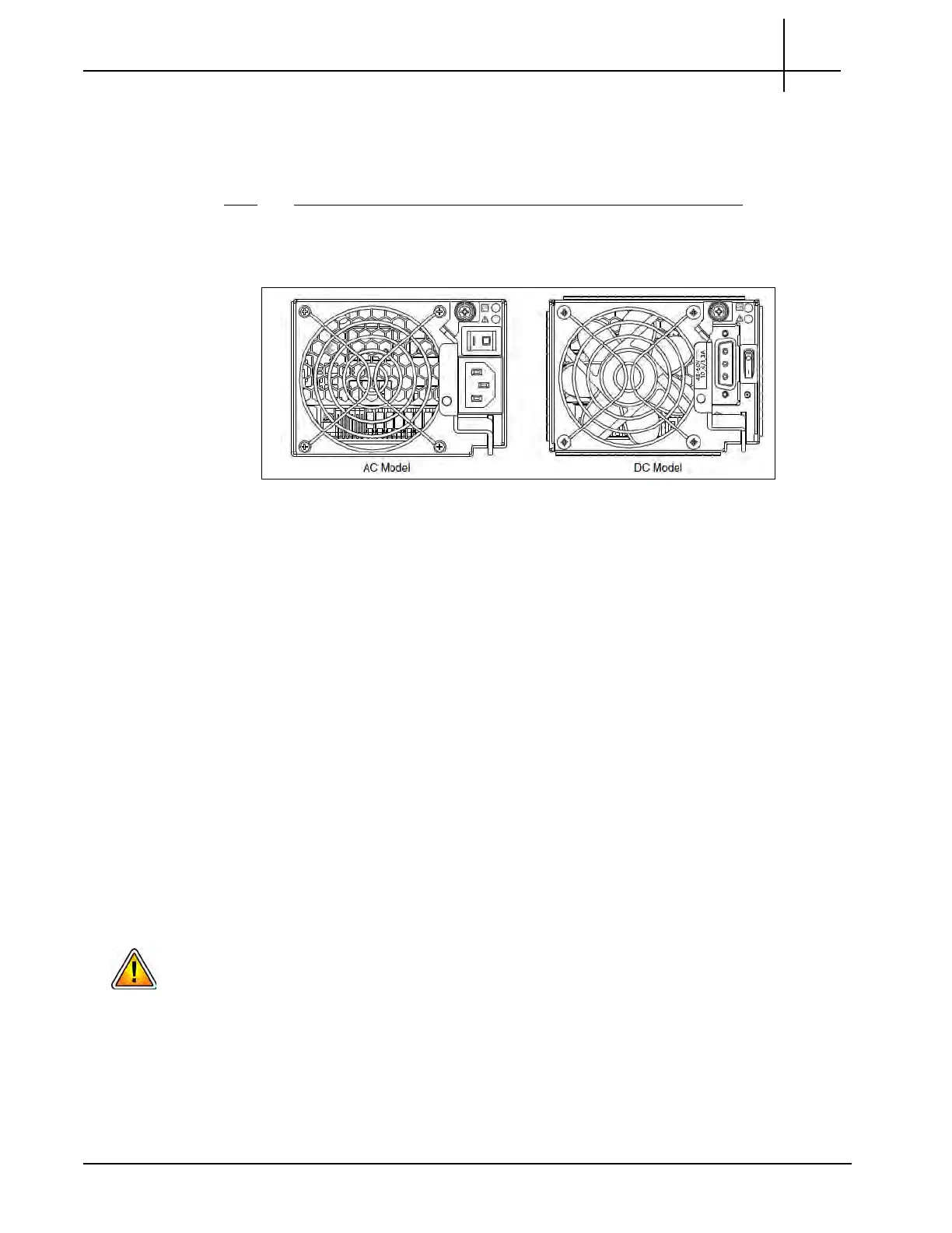
1. Orient the PSU with the AC or DC connector and power switch toward the right,
as shown in Figure C.38.
Figure C.38 - Power Supply Module
2. Verify that the latch is rotated downward to 45 degrees.
3. Slide the module into the power supply s
l
ot as far as it will go.
4. Rotate the PSU latch upward until it is flush
against the PSU face, ensuring that
the connector on the PSU engages the connector inside the chassis.
5. Turn the thumbscrew located at the top of th
e po
wer supply latch clockwise,
until it is finger-tight, to secure the latch to the power supply unit within
the enclosure.
6. Ensure that the main circuit breaker in the rack is shut off.
7. Reconnect the power cables:
For DC power cables:
- Ensure that the DC Module power switches are in the OFF position.
- Attach the cable connector to the DC PSU cable connector and tighten
the screws to attach the cable securely to the DC PSU.
Be sure the DC Plugs do not touch the Grounding Posts (located under the power switches)
to minimize risk of electrical hazard.
For AC power cables:
- Ensure that the AC Module power switches are in th
e OFF position
(if applicable).
Tektronix Communications | For Licensed Users | Unauthorized Duplication and Distribution Prohibited
 Loading...
