G10 Installation Guide 7.13.2 93
A
Rev. 005-140228
Leave enough space in front and in back of an enclosure to allow access to enclosure
components for servicing. Removing a component requires a clearance of at least 15
inches (37 cm) in front of and behind the enclosure.
Refer to Equipment Cooling Requirements on page 168 of Appendix D for details about
Network Equipment Building Systems (NEBS) requirements
.
Example Rack Installations
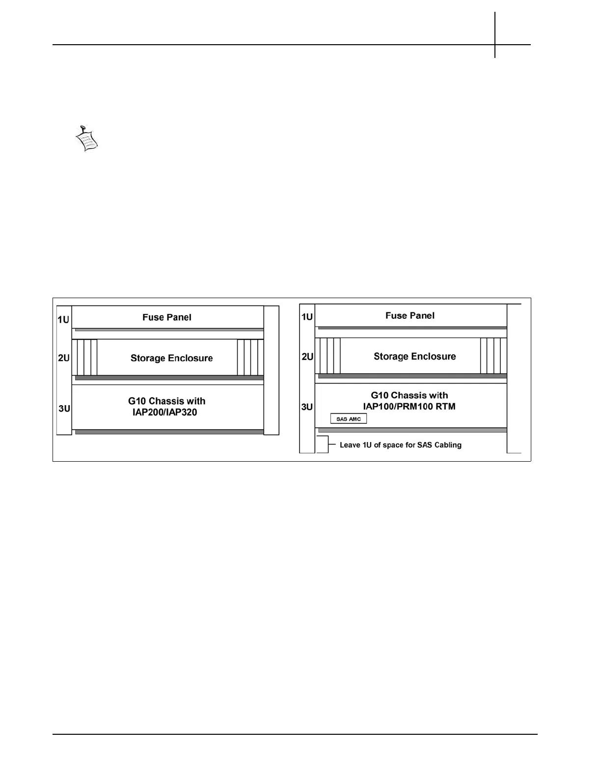
Figure A.1 shows example rack installations of the G10 probe, one controller disk enclosure,
and the fuse panel (fuse panels apply only to
DC power configurations). Tektronix
recommends installing the first controller enclosure above the G10 probe to allow for future
storage expansion (see Figure A.2). For IAP100
/PRM100 RTM configurations, make sure
to leave 1U of space below the G10 to allow for SAS
cabling from the SAS AMC on the
front of the G10 to the back of the controller enclosure.
Figure A.1 - Example Rack Installation
Tektronix Communications | For Licensed Users | Unauthorized Duplication and Distribution Prohibited

 Loading...