G10 Installation Guide 7.13.2 129
C
Rev. 005-140228
If your shelf is powered on, the blue Hot Swap LED illuminates as soon as the
blade is connected to the backplane power pins. When the blade is completely
installed, the blue LED starts to blink. This indicates that the blade announces
its presence to the shelf management controller.
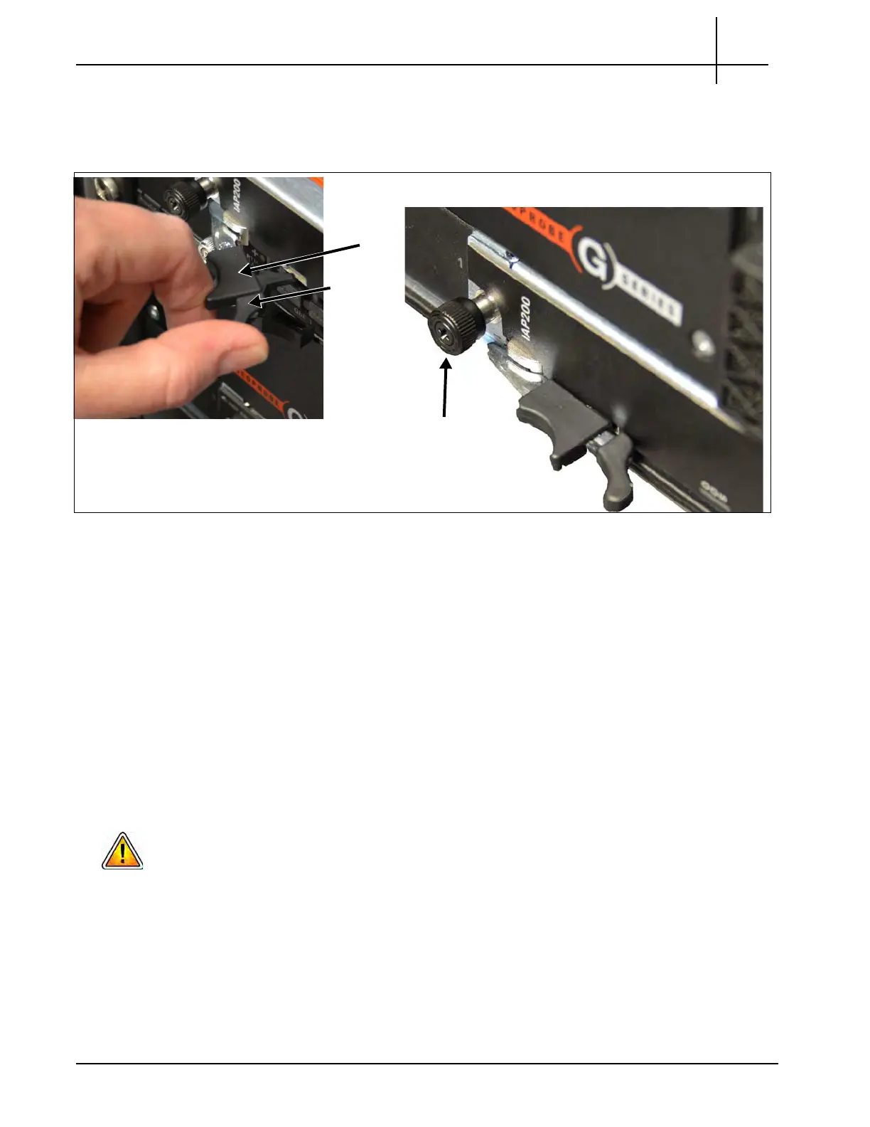
Figure C.21 - IAP Insertion
5. Wait until the blue LED is switched off and
th
en tighten the faceplate screws that
secure the blade to the shelf.
When the LED turns off, this indicates the blade’s payload has been powered
up
and that the blade is active.
Iris Interface Card (IIC100 or IIC200)
This section contains the following procedures for the IIC.
Removing or Resetting the IIC100 or IIC200
Installing the IIC100 or IIC200
If you are upgrading a probe by replacing the IIC100 with the IIC200, refer to the G10
Installation Guide for a detailed procedure.
Tektronix Communications | For Licensed Users | Unauthorized Duplication and Distribution Prohibited
 Loading...
