G10 Installation Guide 7.13.2 45
2
Install Hardware and Power Cabling
Rev. 005-140228
Terminal and Wiring Recommendations
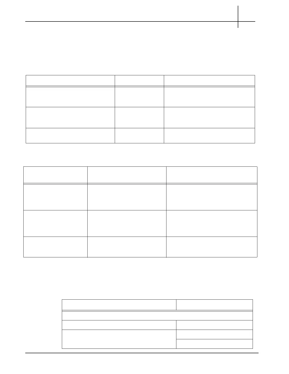
This section provides wiring and lug recommendations for the Fuse Panel. Refer to the G10
Hardware Maintenance Guide for technical specifications of the fuse panel. Table 2.2
provides specifications for wiring and lugs that Te
ktronix provides with the G10.
Table 2.3 contains wiring and lug recommendations for the Fuse Panel.
G10 HARDWARE COMPONENT NAME REFERENCE
Table 2.4 lists the naming conventions used to identify the various G10 components.
Table 2.2 - G10 to Fuse Panel Wiring and Lug Specifications
G10 Terminal Wire Specifications Fuse Panel Lug Specifications
Power Input (-48VDC or -60VDC)
Connect to - Terminal (negative)
#12 AWG Tyco 329697 or equivalent
Connect to the #6 s
c
rew on the fuse
panel
Return
Connect to + Terminal (positive)
#12 AWG Tyco 329697 or equivalent
Connect to the #6 sc
rew on the fuse
panel
Earth Ground
Connect to Burndy YAV102TC10-90 lug
#12 AWG Burndy YAV102TC10-90 or equivalent
Table 2.3 - Fuse Panel Wiring and Lug Recommendations
Terminal Wire Recommendations
(Cus
tomer Provides)
Lug Recommendations
(Tektronix Provides)
Power Input (-48VDC or
-60VD
C)
Use input wire size appropriate for
total output loading on panel
Use #2 AWG for 100A input
Straight dual-hole lugs for 1/4” studs on
5/8”
centers (Panduit LCDN2-14A-Q for
#2 AWG or equivalent)
Return Use input wire size appropriate for
tota
l output loading on panel
Use #2 AWG for 100A input
Straight dual-hole lugs for 1/4” studs on
5/8”
centers (Panduit LCDN2-14A-Q for
#2 AWG or equivalent)
Earth Ground Use #8 AWG or greater 90° dual-hole lugs for #10 studs on 5/8”
center
s (
Burndy YA8CL2TC10-90 or
equivalent)
Table 2.4 - G10 Component Names
Component Current Name
Blades
Carrier Blade (see Iris Interface Cards) CAB100
Iris Interface Cards IIC100
IIC200
Tektronix Communications | For Licensed Users | Unauthorized Duplication and Distribution Prohibited

 Loading...