G10 Installation Guide 7.13.2 44
2
Install Hardware and Power Cabling
Rev. 005-140228
Tektronix equipment, cables, and wiring diagrams comply with industry standard DC
electrical color coding. Please ensure proper cabling if your equipment and cabling
uses nonstandard DC electrical color coding. Improper cabling can cause damage to
equipment or personal injury. Contact Tektronix to request specially labeled power
cables (-48V = Red, Return = Black) for the G10 chassis and the storage enclosures.
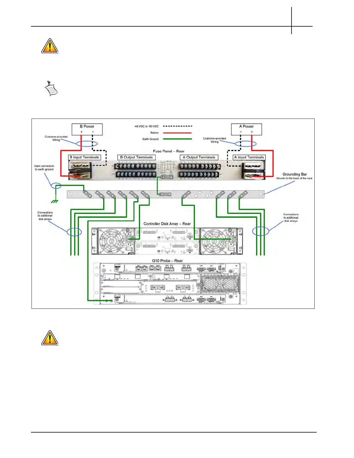
Systems with multiple disk enclosures require a grounding solution that can
adequately ground all units.
Figure 2.29 shows an example grounding solution using
a grounding bar. Note that Figure 2.29 only shows grounding cabling from the
components to the grounding bar; refer to Figure 2.28 for power cabling from the
components to the fuse panel.
Figure 2.29 - Example Grounding Solution
Tektronix equipment, cables, and wiring diagrams comply with industry standard DC
electrical color coding. Please ensure proper cabling if your equipment and cabling
uses nonstandard DC electrical color coding. Improper cabling can cause damage to
equipment or personal injury. Contact Tektronix to request specially labeled power
cables (-48V = Red, Return = Black) for the G10 chassis and the storage enclosures.
2. Insert 15 A GMT fuses into the slots on the front of the fuse panel
corresponding to the output terminals that you used for the G10 and the storage
enclosures at the rear of the fuse panel.
3. Continue with Ethernet cabling in Chapter 3.
Tektronix Communications | For Licensed Users | Unauthorized Duplication and Distribution Prohibited
 Loading...
