G10 Installation Guide 7.13.2 32
2
Install Hardware and Power Cabling
Rev. 005-140228
Two-Post Rack, Mid Mount
The storage enclosures must be securely mid-mounted to the two-post rack (also known as
center mount). The provided brackets support mounting in a standard 19-inch wide rack. If
mounting the chassis to a 23-inch wide rack, you must first install extension brackets before
securing it to the rack.
Step Action
1. Determine the location in the rack in which you will install the storage enclosure
(see Example Rack Installations).
For IAP100/PRM100 RTM configurations, make sure to leave 1U of space below the
G10 to allow for SAS cabling from the SAS AMC on the font of the G10 to the back of
the controller enclosure(s).
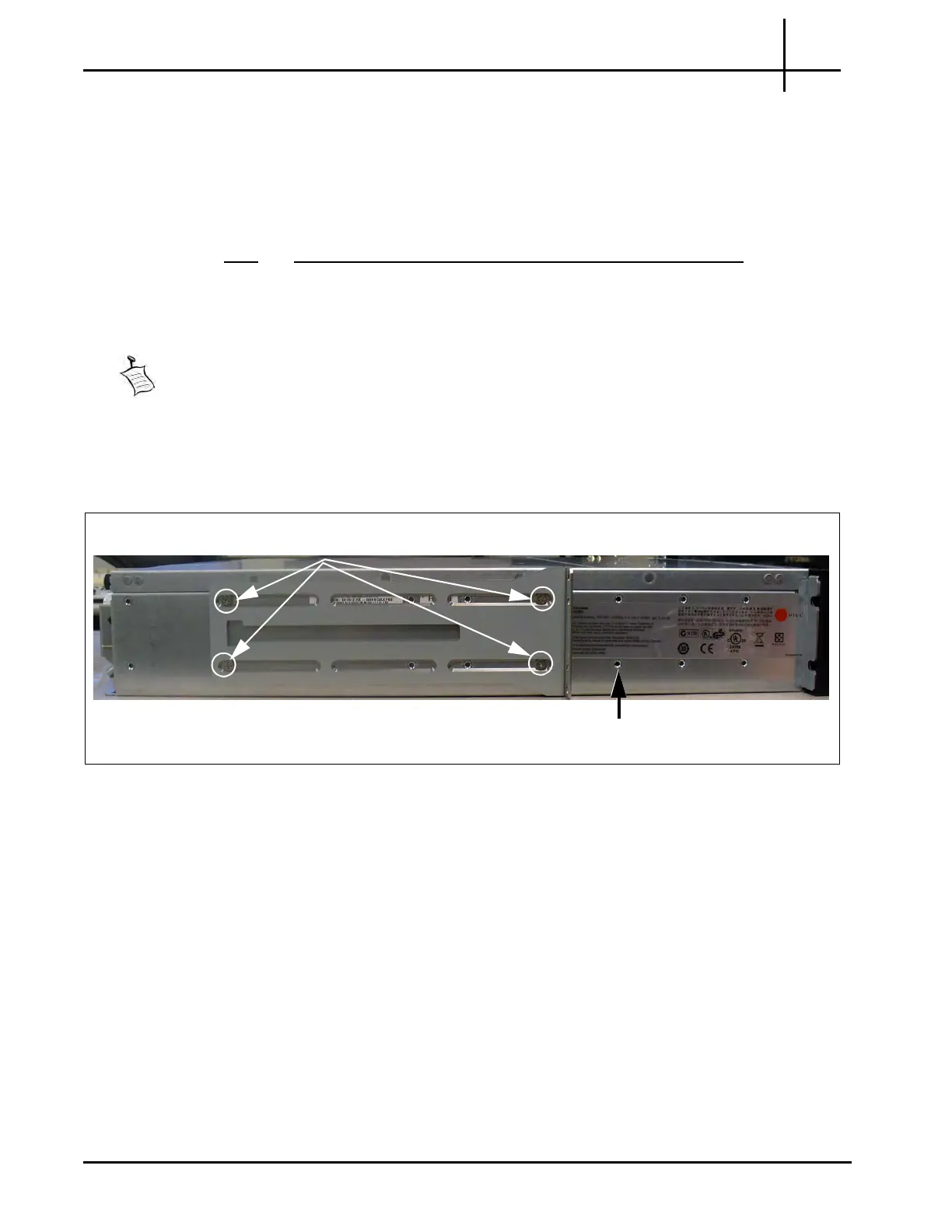
2. Install the main bracket onto the side of the storage enclosure using four
bracket screws (Figure 2.15). The bracket position shown is for
3” to 4” rack
post depth. For rack post depths of 5” to 7”, align the front bracket screws at the
third sc
rew position.
Figure 2.15 - Front Rackmount Bracket Placement on G10 Chassis
Bracket Screw Placement for
3” to 4” rack post depth
For 5” to 7” rack post depth,
align front of bracket here
Tektronix Communications | For Licensed Users | Unauthorized Duplication and Distribution Prohibited

 Loading...