G10 Installation Guide 7.13.2 41
2
Install Hardware and Power Cabling
Rev. 005-140228
DC Units
The DC power cables for the storage enclosure are shipped with plugs already attached.
Refer to Storage Enclosure Bonding and Grounding Requirements of Appendix D for details
about NEBS requirements.
Figure 2.26 - Storage Enclosure DC Plugs
Connect all cabling on the G10 and storage enclosure before connecting the cables
to the Fuse Panel to minimize risk of electrical hazard. Make sure that the external
power feeds you plan to attach are powered off and cannot be switched on while you
are working.
Step Action
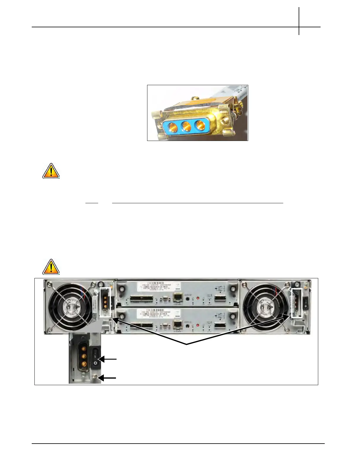
1. Ensure that the DC Module power switches are in the OFF position
(Figure 2.27).
2. Plug the DC power cables into the power connectors on the rear of the storage
e
nc
losure (Figure 2.27).
Be sure the DC Plugs do not touch the Grounding Posts (located under the power
switches) to minimize risk of electrical hazard.
Figure 2.27 - Storage Enclosure Rear View
3. Fasten the screws on both sides of the plugs to secure them to the unit.
4. Proceed to Fuse panel power cabling on page 42.
DC Power Connectors
Grounding Post
ON/OFF Switch
Tektronix Communications | For Licensed Users | Unauthorized Duplication and Distribution Prohibited

 Loading...