G10 Installation Guide 7.13.2 86
5
Connect G10 to the Monitored Network
Rev. 005-140228
2. After the cables are connected, verify that the ACT and LNK LEDs are ON.
3. Call Tektronix Service and Delivery to confirm the successful G10 installation
(refer
to page 2).
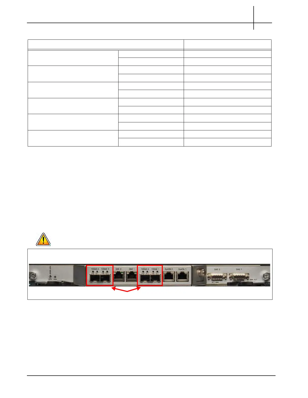
10 Gigabit Ethernet Connections (TRM100 RTM)
You connect the 10G Ethernet to the rear of the G10 on the TRM100 RTM. Figure 5.7 shows
the four 10-Gb Ethernet ports. This section descr
ibes cabling for the TRM100 RTM when
paired with the IIC100.
If your configuration pairs the TRM100 RTM with the IIC200, connect the 10G inputs to
the IIC200, NOT the TRM100 RTM. Refer to
page 77 for details.
Figure 5.7 - 10Gigabit Ethernet Ports
Monitored Interface 3 “Link 3” TX GbE 3 RX (left)
RX
GbE 3 TX (right)
M
onitored Interface 4 “Link 4” TX GbE 4 RX (left)
RX GbE 4 TX (right)
Monitored Interface 5 “Link 5” TX GbE 5 RX (left)
RX GbE 5 TX (right)
Monitored Interface 6 “Link 6” TX GbE 6 RX (left)
RX GbE 6 TX (right)
Monitored Interface 7 “Link 7” TX GbE 7 RX (left)
RX GbE 7 TX (right)
Monitored Interface 8 “Link 8” TX GbE 8 RX (left)
RX GbE 8 TX (right)
Table 5.5 - G10 1G Ethernet Connections - Mirror/Span (Continued)
Monitored Network G10 1G Ethernet Connections
TRM100 RTM
4 10G Connections
Tektronix Communications | For Licensed Users | Unauthorized Duplication and Distribution Prohibited

 Loading...