G10 Installation Guide 7.13.2 85
5
Connect G10 to the Monitored Network
Rev. 005-140228
1G Ethernet Cabling for Mirror/Span Ports
Perform the following to connect Ethernet cabling to the monitored network using optical taps/
splitters.
Step Action
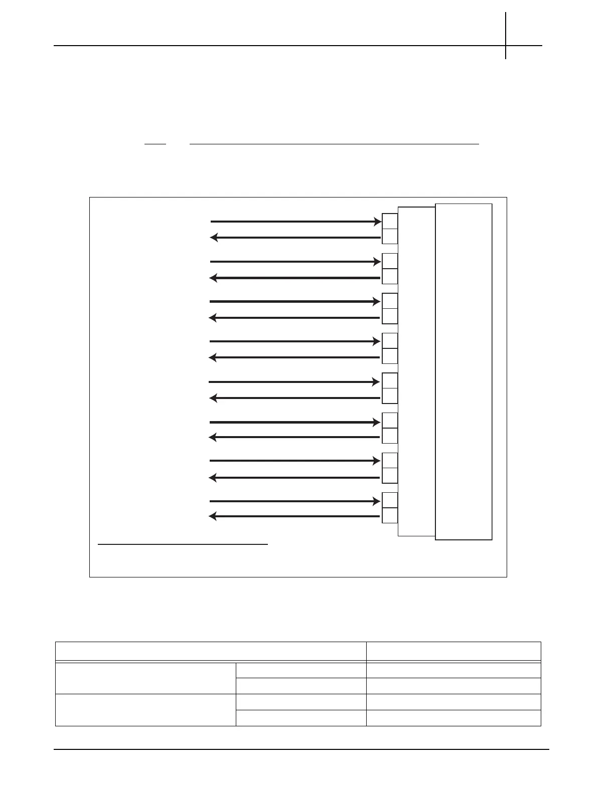
1. Use Figure 5.6 and Table 5.5 to connect the monitored network to the G10 1G
Ethernet connections for mirror/span ports.
Figure 5.6 - G10 1G Ethernet Connec
tions - Mirror/Span
GbE 1
GbE 2
GbE 3
GbE 4
GbE 5
GbE 6
GbE 7
GbE 8
Rx
Tx*
Rx
Tx*
Rx
Tx*
Rx
Tx*
Rx
Tx*
Rx
Tx*
Rx
Tx*
Rx
Tx*
8x1G Ports
on Iris
Interface
Card
Rx
Tx/Rx**
Rx
Rx
Rx
Rx
Rx
Rx
Rx
Monitored Interface
"Link 1"
Monitored Interface
"Link 2"
Monitored Interface
"Link 3"
Monitored Interface
"Link 4"
Monitored Interface
"Link 5"
Monitored Interface
"Link 6"
Monitored Interface
"Link 7"
Monitored Interface
"Link 8"
Tx/Rx**
Tx/Rx**
Tx/Rx**
Tx/Rx**
Tx/Rx**
Tx/Rx**
Tx/Rx**
*
The G10 probe transmits light only to keep port active.
** Aggregated data from customer monitored links.
Table 5.5 - G10 1G Ethernet Connections - Mirror/Span
Monitored Network G10 1G Ethernet Connections
Monitored Interface 1 “Link 1” TX GbE 1 RX (left)
RX GbE 1 TX (right)
Monitored Interface 2 “Link 2” TX GbE 2 RX (left)
RX GbE 2 TX (right)
Tektronix Communications | For Licensed Users | Unauthorized Duplication and Distribution Prohibited

 Loading...