G10 Installation Guide 7.13.2 82
5
Connect G10 to the Monitored Network
Rev. 005-140228
MONITORED LINK CABLING (IIC100)
This section describes Ethernet connections and cabling for the IIC100; for
information for the IIC200, refer to
Monitored Link Cabling (IIC200).
To accurately monitor links, a minimum signal strength is re
quired at each G10 input port. The
signal strength requirement is broad enough to allow some optical taps and splitters. The
inputs must comply with Table B.1 in Appendix B and can be verified with optical light
meters.
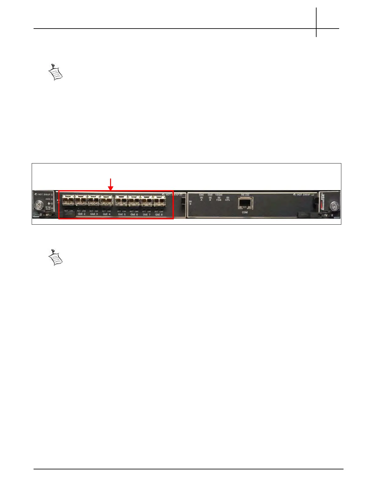
1 Gigabit Ethernet Connections (IIC100)
You connect the 1G Ethernet cable to the front of the G10 on the IIC100 (Figure 5.4).
Figure 5.4 - IIC100 1G Ethernet Connections
Refer to Appendix B SFP Reference for details about installing and maintaining SFP
modules.
Tektronix Communications | For Licensed Users | Unauthorized Duplication and Distribution Prohibited

 Loading...