System Manual 6. Maintenance
76.7300FP11/2, Rev A 8/09 Page 2-99
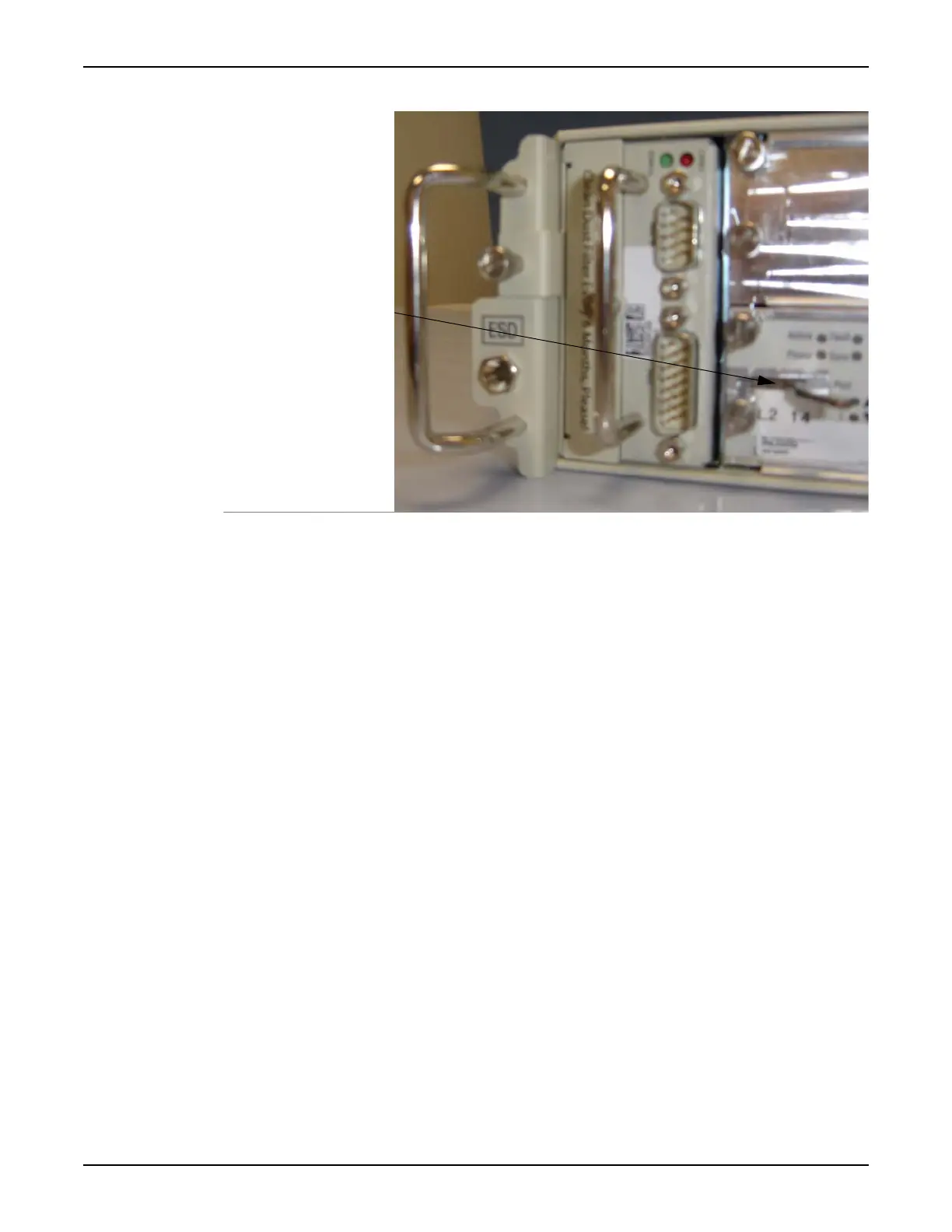
Figure 6.9 10G Switch Module Ejector Latch
__ 10. Push the ejector latches inward and pull the module out of the shelf.
__ 11. Store the module in its antistatic packaging.
__ 12. Remove the replacement 10G Switch module from its antistatic
packaging.
__ 13. Install the replacement 10G Switch module in slot 2 of the shelf, being
sure to secure the module’s ejector latches. Refer to Installing the
Modules (Tellabs 7345 Switch only), page 2-56 for guidelines.
__ 14. Securely fasten the replacement 10G Switch module to the shelf by
tightening the module’s thumbscrews.
__ 15. Ensure the SFP/XFP bales (the latch on the cable side of the
transceiver) are in the open position. Refer to Figure 5.20, page 2-65.
__ 16. Reinsert the SFPs/XFPs into the 10G Switch module sockets and
carefully slide the SFP into the socket until its connector is fully seated.
Close the bale.
• The upper-row of 10G Switch module SFP/XFP sockets require
that transceivers be installed bale-side up. Refer to Figure 5.20,
page 2-65 and Figure 5.21, page 2-66.
• The lower-row of 10G Switch module SFP/XFP sockets require
that transceivers be installed bale-side down. Refer to Figure 5.20,
page 2-65 and Figure 5.21, page 2-66.
Do not force SFPs/XFPs into sockets.
__ 17. Remove dust caps from fiber cables, and reconnect all cables to the
replacement 10G Switch module. Refer to Fiber Optic Cleaning
Procedures, page 2-109 for more information.
__ 18. Restore the local backup by following the steps in Restore a Local
Backup, page 2-89. Refer to Initializing the Tellabs 7300 NE,
page 2-75 if you need to set the IP address.
 Loading...