System Manual 5. Installation
76.7300FP11/2, Rev A 8/09 Page 2-71
__ 3. Set the PC network interface card to an IP address on the same
subnet as the default IP address of the Tellabs 7345 Switch. For
example, 10.0.0.2.
5.67 Local Management (MGT) port defaults are as follows:
• auto-negotiation
• IP Address = 10.0.0.1
• Subnet Mask = 255.255.255.0
Connecting Through the Ethernet Management Port (MGT1) - Tellabs 7325 Switch
5.68 The Tellabs 7325 Switch supports 10/100BASE-T Ethernet interfaces
through RJ-45 connectors on the front of the system.
5.69 Connect the Ethernet management cables to the Tellabs 7325 Switch by
performing the following steps:
Note: For a listing of facility cables, refer to Table 5.1, page 2-46.
__ 1. Connect the Ethernet cable for management of the Tellabs 7325
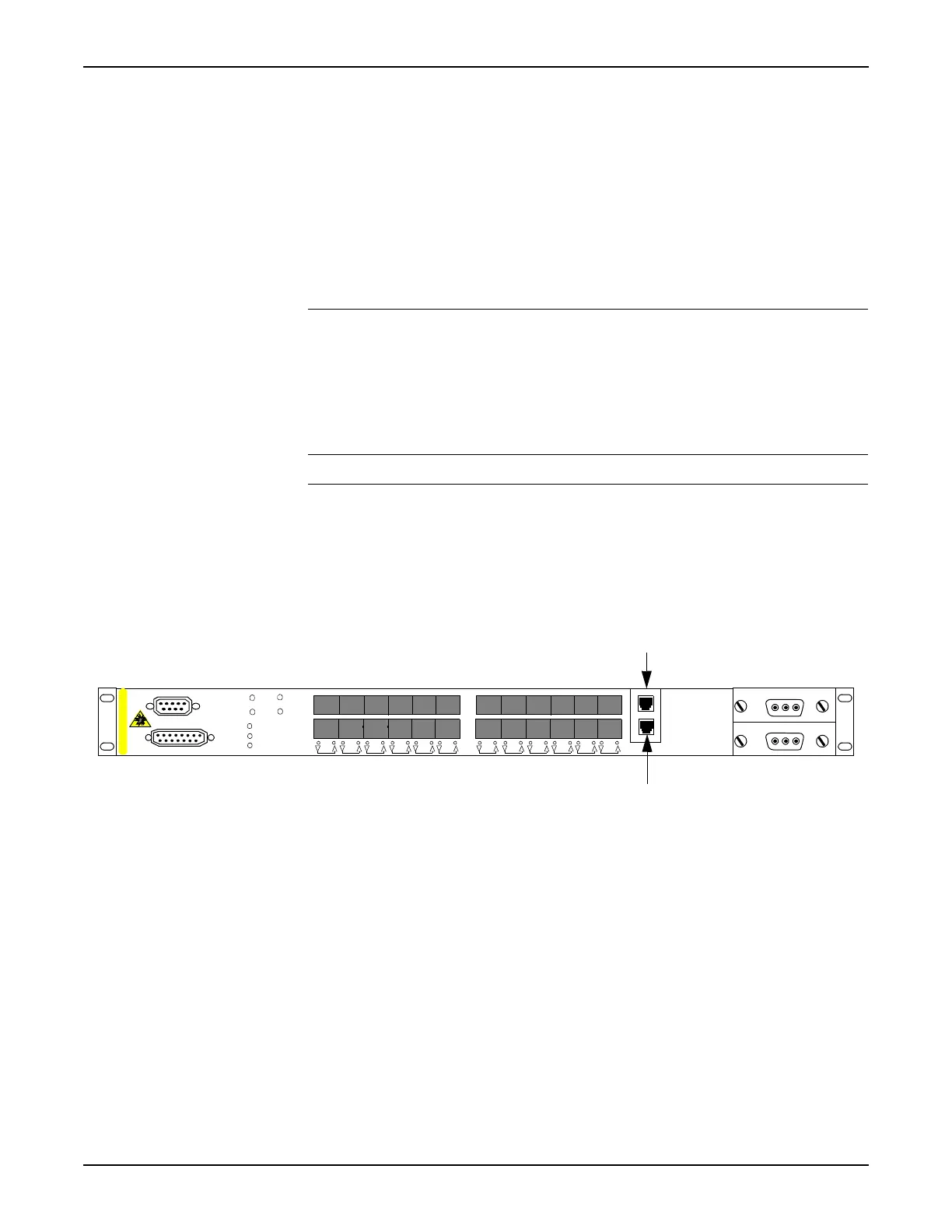
Switch to the MGT port. Refer to Figure 5.27, page 2-71.
__ 2. Connect a PC Ethernet connection to the other end of the cable.
Figure 5.27 Location of MGT and CT Ports in the Tellabs 7325 Switch
__ 3. Set the PC network interface card to an IP address on the same
subnet as the default IP address of the Tellabs 7325 Switch. For
example, 10.0.0.2.
5.70 Local Management (MGT) port defaults are as follows:
• auto-negotiation
• IP Address = 10.0.0.1
• Subnet Mask = 255.255.255.0
Active
Fault
Sync
Power
Minor
Major
Critcal
8
1
.
7
3
2
5
A
-
R
5
C
T
M
G
T
12 5634 78 910 11 12 13 14 15 16 17 18 19 20 21 22 23 24
SYNC
Alarm
CLASS 1 LASER PRODUCT
MGT Port
CT Port
 Loading...