System Manual 4. System Components
76.7300FP11/2, Rev A 8/09 Page 2-27
Tellabs 7345 Shelf
4.06 The Tellabs 7345 Switch consists of one 19-inch, 7-slot shelf designed for
installation in a 19-inch datacom rack, ETSI rack, or 23-inch North American
seismic rack with mounting ears. The Tellabs 7345 Switch architecture is designed
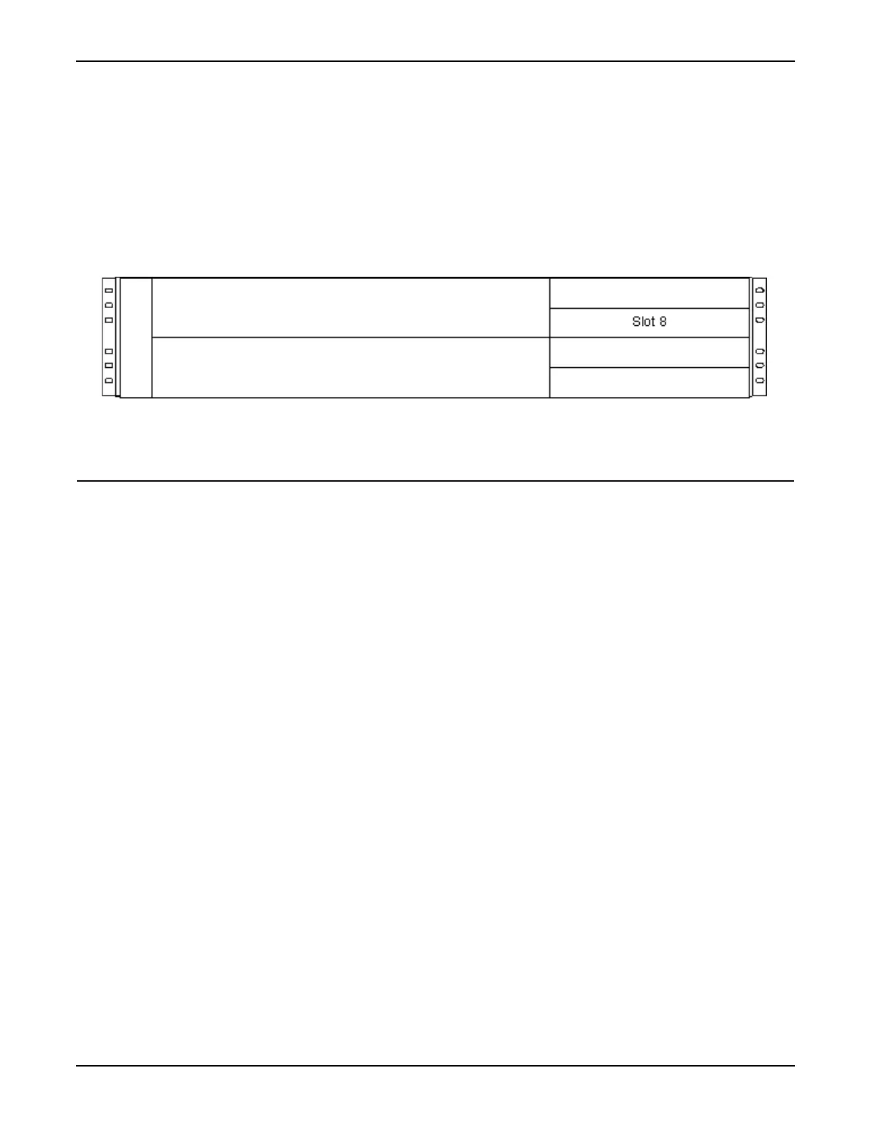
to help conserve space while providing CO-level reliability. For a diagram of the
Tellabs 7345 Switch backplane, refer to Figure 4.2, page 2-27.
4.07 For Tellabs 7345 shelf specifications, refer to Specifications, page 2-8.
Figure 4.2 Tellabs 7345 Shelf Backplane Slots
10G Switch Module
4.08 This section describes the features and circuitry of the
82.731150A/B/C-R5 switch module used in the Tellabs 7345 Switch.
4.09 The 10G Switch module provides:
• 44 Gbps Ethernet switch capability at a minimum
• support for uplink and client facility redundancy
• (2) 10 GbE pluggable LAN PHY XFP uplinks
• (24) 1 GbE pluggable 10/100/1000 SFPs
• facility and terminal loopback
4.10 The 10G Switch module supports a non-blocking switch fabric for the 44G
of interfaces that are supported by that module. The Tellabs 7345 Switch can
support 24 GbE interfaces and two 10 GbE interfaces, depending on the switch
module option installed. The Tellabs 7345 Switch can support up to eight GbE
aggregated traffic via link aggregation.
4.11 The 10G Switch module is available in three configurations. Refer to
Figure 4.3, page 2-28.
Slot 4
Slot 2
Slot 9
Slot 7
Slot 1
Slot 6

 Loading...