5. Installation System Manual
Page 2-62 8/09 76.7300FP11/2, Rev A
Connecting DC Power to the Tellabs 7300 NE
5.48 Follow the procedures in this section to connect DC power to the Tellabs
7300 NE.
Tools 5.49 The following tools are required to complete this procedure:
__ indelible marker (black)
__ Phillips-head screwdriver
__ 5/16-inch nut driver
Materials 5.50 The following materials are required to perform this procedure per device:
__ up to two–Power Cable Kits (Tellabs part number 81.7300PCBLB-R5
for the Tellabs 7345 Switch and Tellabs part number
81.7325PCBLB-R5 for the Tellabs 7325 Switch)
__ one–customer supplied power distribution source
or
__ one–Fuse Panel (Tellabs part number 81.71020FP5-5-R5)
Note: Refer to Table 2.3, page 2-9 for input power requirements for the Tellabs
7345 Switch and Table 2.4, page 2-9 for input power requirements for the
Tellabs 7325 Switch.
5.51 Refer to Figure 5.17, page 2-62 for the power cable connections required
to perform this procedure on the Tellabs 7345 Switch and to Figure 5.18, page 2-63
for the power cable connections required to perform this procedure on the Tellabs
7325 Switch.
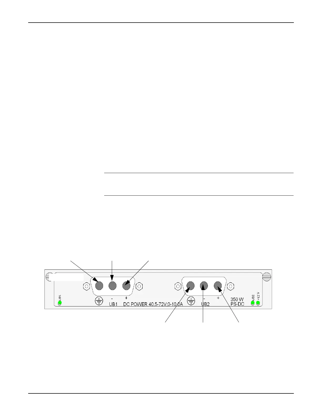
Figure 5.17 Tellabs 7345 Switch PSU Module Connector Pins
Pin 1: N/C
Pin 2: -48 VDC Pin 3: Return (RTN)
Pin 1: N/C Pin 2: -48 VDC Pin 3: Return (RTN)

 Loading...