System Manual 5. Installation
76.7300FP11/2, Rev A 8/09 Page 2-61
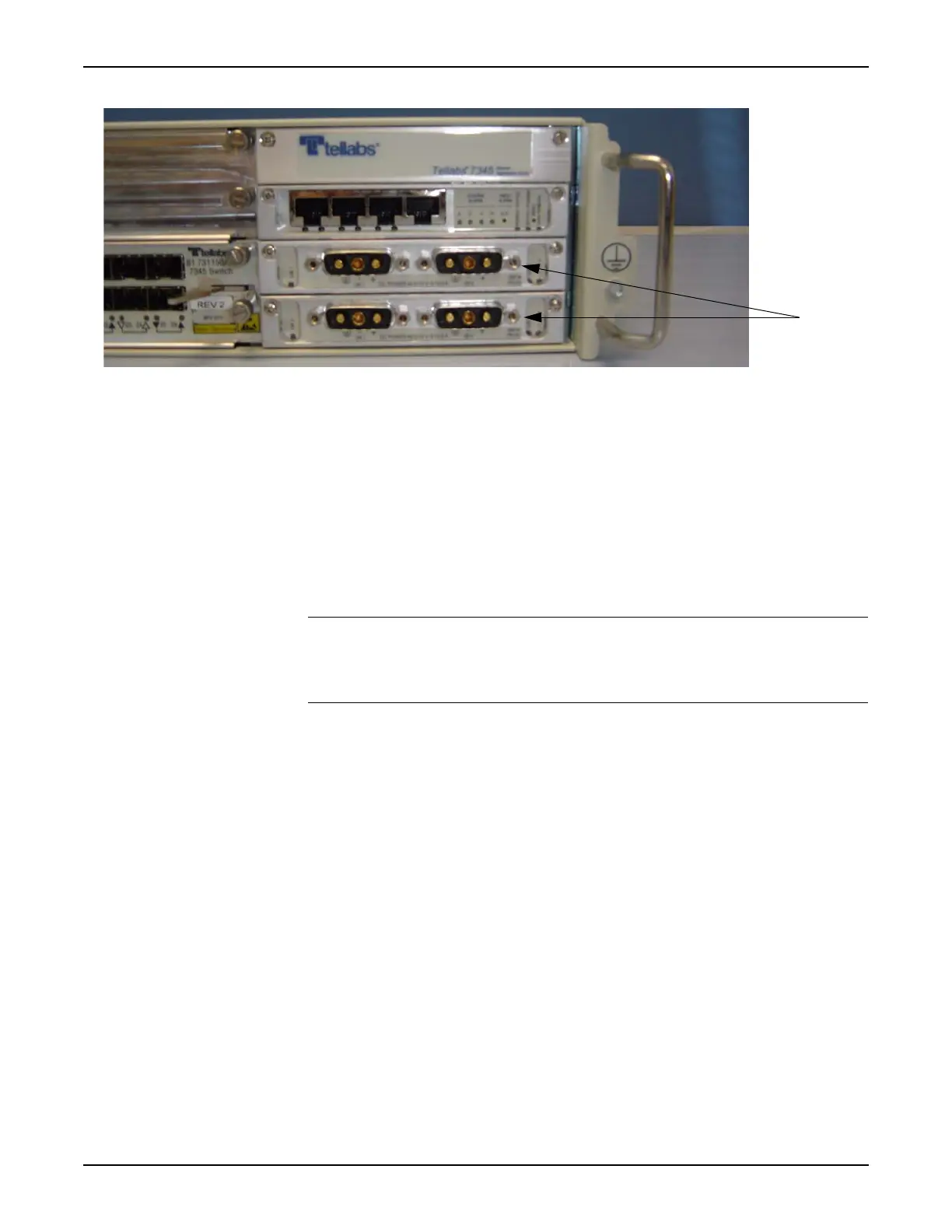
Figure 5.16 Location of PSUs in Tellabs 7345 Switch
__ 2. If dual PSUs are installed in slots 6 and 7 of the Tellabs 7345 Switch,
connect the DC power cable to the UB1 connector on the 7345 PSU
located in slot 6 and connect the second DC power cable to the UB1
connector on the 7345 PSU located in slot 7. Secure the DC power
connector to the 7345 power supply.
__ 3. If only a single Power Converter is installed in the Tray, connect the
DC power cable to UB1 of the 7345 PSU. Secure the DC power
connector to the 7345 power supply.
__ 4. Connect the AC power cables to a suitable AC power source. Verify
that the appropriate LED (UB1, UB2, or both depending on the power
configuration) is green.
Note: To service the Power Converter, the switch must be powered down and
the Power Converter Tray removed from the rack. Refer to step 5,
page 2-63 for procedures to power down the switch before disconnecting
the AC power source from the Power Converter(s).

 Loading...