System Manual 5. Installation
76.7300FP11/2, Rev A 8/09 Page 2-63
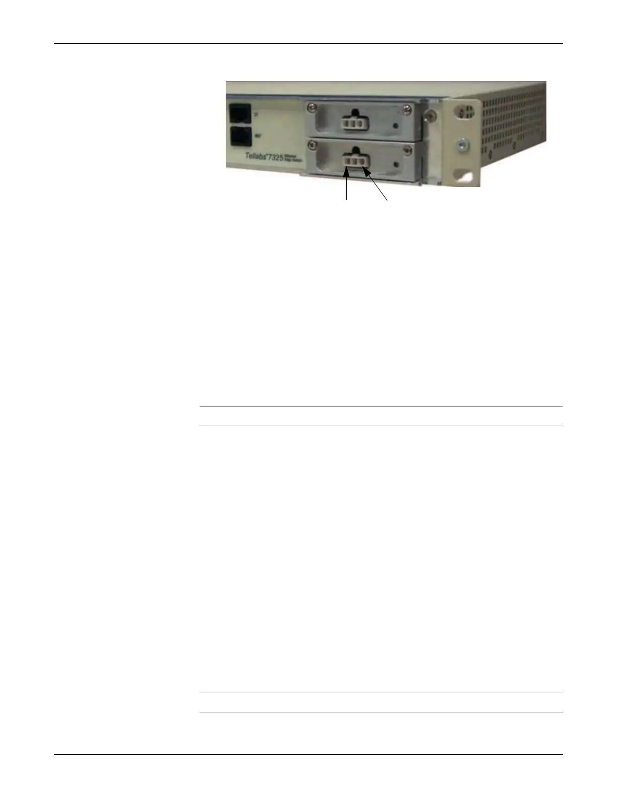
Figure 5.18 Tellabs 7325 Switch PSU Module Connector Pins
__ 1. Throughout this procedure follow your company procedures for
connecting power.
__ 2. Verify that the power source has up to two available power
connections (terminal posts). Each NE requires up to two power
connections, A-side and B-side.
__ 3. Obtain a power cable for the NE. Refer to Materials, page 2-62.
__ 4. Make sure that the -48/60 Vdc (tolerance -40.5 to -72 Vdc) power is
present at the source.
__ 5. Disconnect power by either switching off or removing the fuses from
the source.
Note: There is no built-in power switch on the Tellabs 7300 NE.
__ 6. Perform the applicable substeps below:
(Tellabs 7345 NE only)
__ Connect the power supply cable to the DC input plug (D-sub).
__ Tighten screws on D-sub to PSU.
(Tellabs 7325 NE only)
__ Connect the power supply cable to the Molex-type connector.
__ 7. Route the power cable to the side of the rack and up to the power
source.
__ 8. Lace the power cable to the rack as you go.
__ 9. Label the Power A cable. Follow company policy when labeling power
cables.
__ 10. Attach the red (-48 Vdc) and black (-48 RTN) ends of the cable to the
-48Vdc and -48 RTN locations on the GMT fuse panel. The Tellabs
GMT fuse panel has #6 screw terminals.
Note: Ensure that the poles are correct when you connect the power cable.

 Loading...