System Manual 5. Installation
76.7300FP11/2, Rev A 8/09 Page 2-49
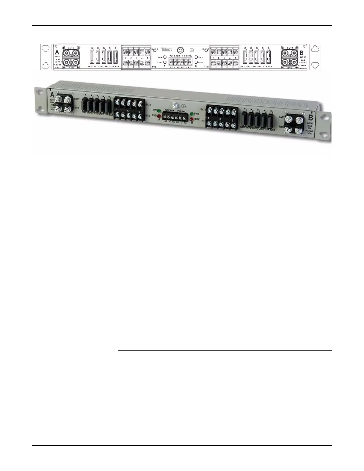
Figure 5.1 Fuse Panel
Tools and Materials 5.25 The following tools and materials are required to complete this procedure:
__ Phillips-head screwdriver
__ 5/16 inch nut driver
__ Fuse Panel (Tellabs part number 81.71020FP5-5-R5)
5.26 Perform the following procedure to install a Fuse Panel in an equipment
rack or customer supplied equipment rack:
__ 1. Unpack the Fuse Panel (Tellabs part number 81.71020FP5-5-R5).
__ 2. Using the screws provided, attach the appropriate mounting ears to
the device (21-inch or 23-inch).
- 81.73ETSI-B-R6 - 21 inch 1RU ETSI Mounting Adapter Kit
- 81.73NEBS-B-R6 - 23 inch 1RU NEBS Mounting Adapter Kit
__ 3. Determine the appropriate position in the rack. The Fuse Panel is
typically installed at the top of the rack.
__ 4. Position the Fuse Panel against the rack.
__ 5. Secure the Fuse Panel to the left side of the rack.
__ 6. Secure the Fuse Panel to the right side of the rack.
Connecting the Fuse Panel to the BDFB
Tools 5.27 The following tools are required to complete this procedure:
__ wire stripper
__ indelible marker (black)
__ cutter
__ lug crimper (Burndy Y8MRB-1)

 Loading...