System Manual 5. Installation
76.7300FP11/2, Rev A 8/09 Page 2-73
Alarm Wiring
5.73 Follow the steps below to connect alarm wiring.
__ 1. Connect the DB-15 alarm cable to the alarm interface on the Fan
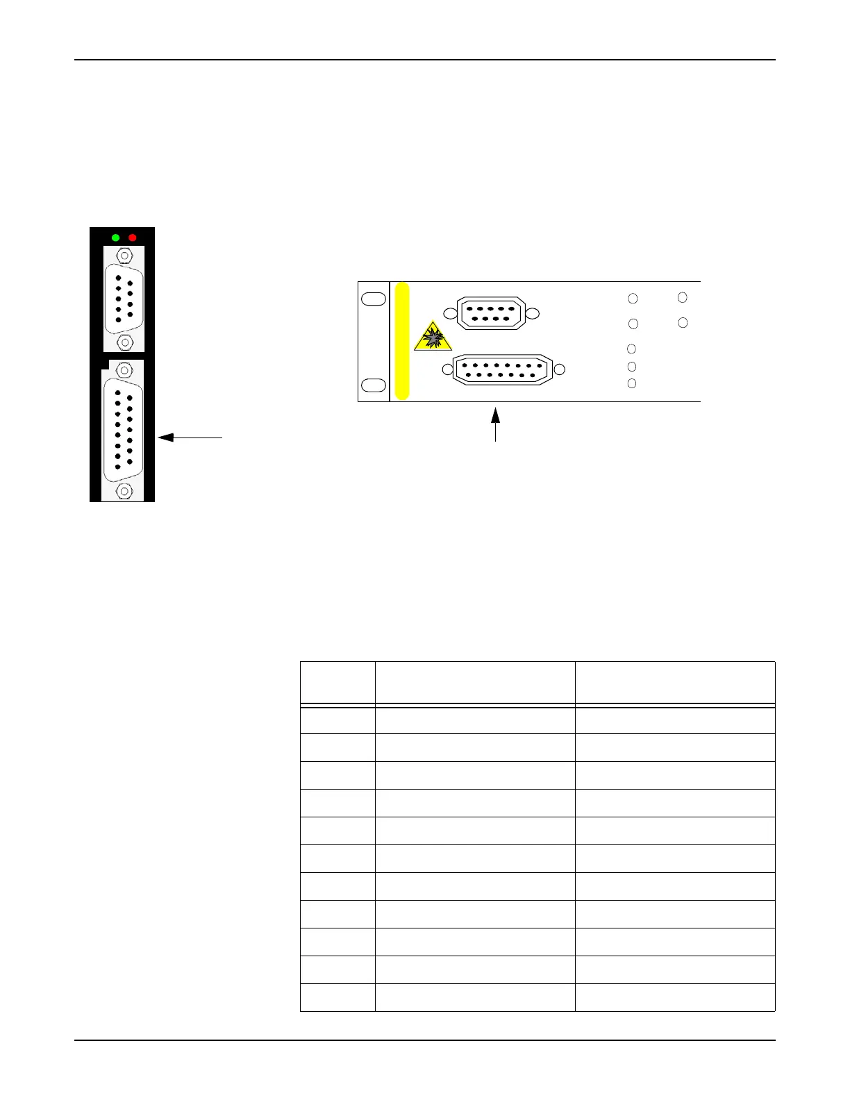
Module. Refer to Figure 5.28, page 2-73.
Figure 5.28 Location of Alarm Interface on Fan Module
__ 2. Connect the stub end of the cable to the customer-supplied external
alarm connections (refer to Table 5.4, page 2-73 for alarm pinouts and
to Table 5.5, page 2-74 for the pinout of the 250.004x cable).
SYNC
ALARM
POWER
FAULT
Alarm interface
Tellabs 7345 Switch
Active
Fault
Sync
Power
Critcal
Major
Minor
SYNC
Alarm
CLASS 1 LASER PRODUCT
Alarm interface
Tellabs 7325 Switch
Table 5.4 Pinout for DB-15 Connector
Pin
Number Signal Name Usage
1 AUX-ALARM0_In aux1 (Env Alarm Input 1)
2 AUX-ALARM1_In aux2 (Env Alarm Input 2)
3 AUX-ALARM2_In aux3 (Env Alarm Input 3)
4 AUX-ALARM3_In aux4 (Env Alarm Input 4)
5 RA_Common Rack Alarm Common
6 RA_A Rack Alarm CR Output
7 RA_R Rack Alarm MN Output
8GND GND
9 AUX-ALARM0_Out aux5 (Ext Contact Output 5)
10 AUX-ALARM1_Out aux6 (Ext Contact Output 6)
11 AUX-ALARM2_Out aux7 (Ext Contact Output 7)

 Loading...