5. Installation System Manual
Page 2-70 8/09 76.7300FP11/2, Rev A
5.63 Tellabs recommends the following for field terminating CAT5e cables:
• Use compatible CAT5e 24 AWG solid twisted pair cable with
compatible RJ-45 connectors made for 24 AWG solid twisted pair
cable when terminating in the field. Do not mix CAT5e solid cable with
RJ-45 connectors made for 24 AWG stranded cable.
• Use the manufacturer recommended CAT5e crimper for the type of
RJ-45 connectors that are being terminated. Some CAT5e crimpers
do not support specific manufacturer’s RJ-45 connectors.
• Once the cable has been terminated following the TIA/EIA-568-B
standard, use a CAT5e cable tester to verify the following:
- Test the cable for shorts, opens, mis-wires, reversal, and split
pairs.
- Length measurement.
Management Connections
5.64 You can access the system through either the Ethernet Management Port
(MGT1) or the Serial RS-232 port (CT) on the CMCC module on the Tellabs 7345
Switch and on the front of the Tellabs 7325 Switch enclosure.
Connecting Through the Ethernet Management Port (MGT1) - Tellabs 7345 Switch
5.65 The 10G Switch module supports 10/100BASE-T Ethernet interfaces
through RJ-45 connectors on the front panel.
5.66 Connect the Ethernet management cables to the Tellabs 7345 Switch by
performing the following steps:
Note: For a listing of facility cables, refer to Table 5.1, page 2-46.
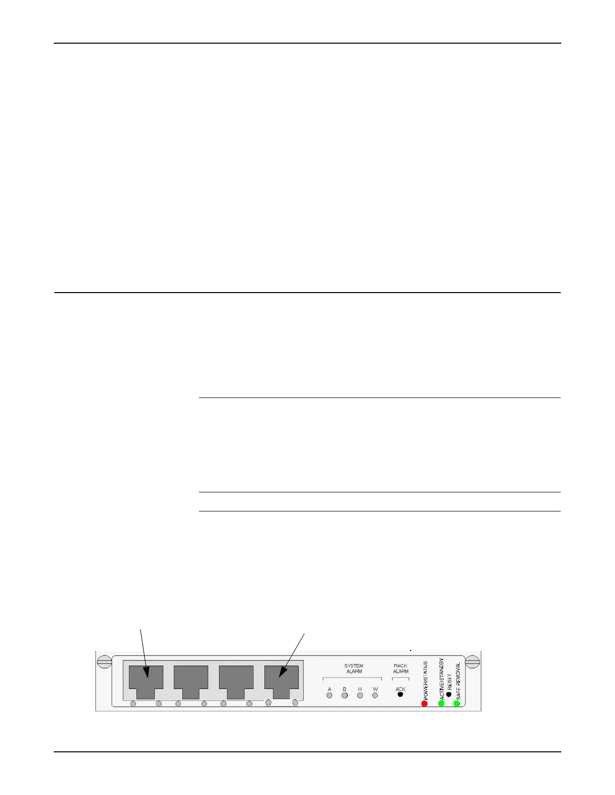
__ 1. Connect the Ethernet cable for management of the Tellabs 7345 shelf
to the MGT1 port on the CMCC module. Refer to Figure 5.26,
page 2-70.
__ 2. Connect a PC Ethernet connection to the other end of the cable.
Figure 5.26 CMCC Module in the Tellabs 7345 Switch
Management Ethernet connection (MGT1)
CT connection

 Loading...