MMWAVEICBOOST
www.ti.com
14
SWRU546C–October 2018–Revised April 2020
Submit Documentation Feedback
Copyright © 2018–2020, Texas Instruments Incorporated
mmWaveICBoost and Antenna Module
To install the devices:
1. Download the latest FTDI and XDS110 drivers available in the mmWave SDK package.
2. Right click on these devices.
3. Update the drivers by pointing to the location where the FTDI and XDS110 drivers are downloaded.
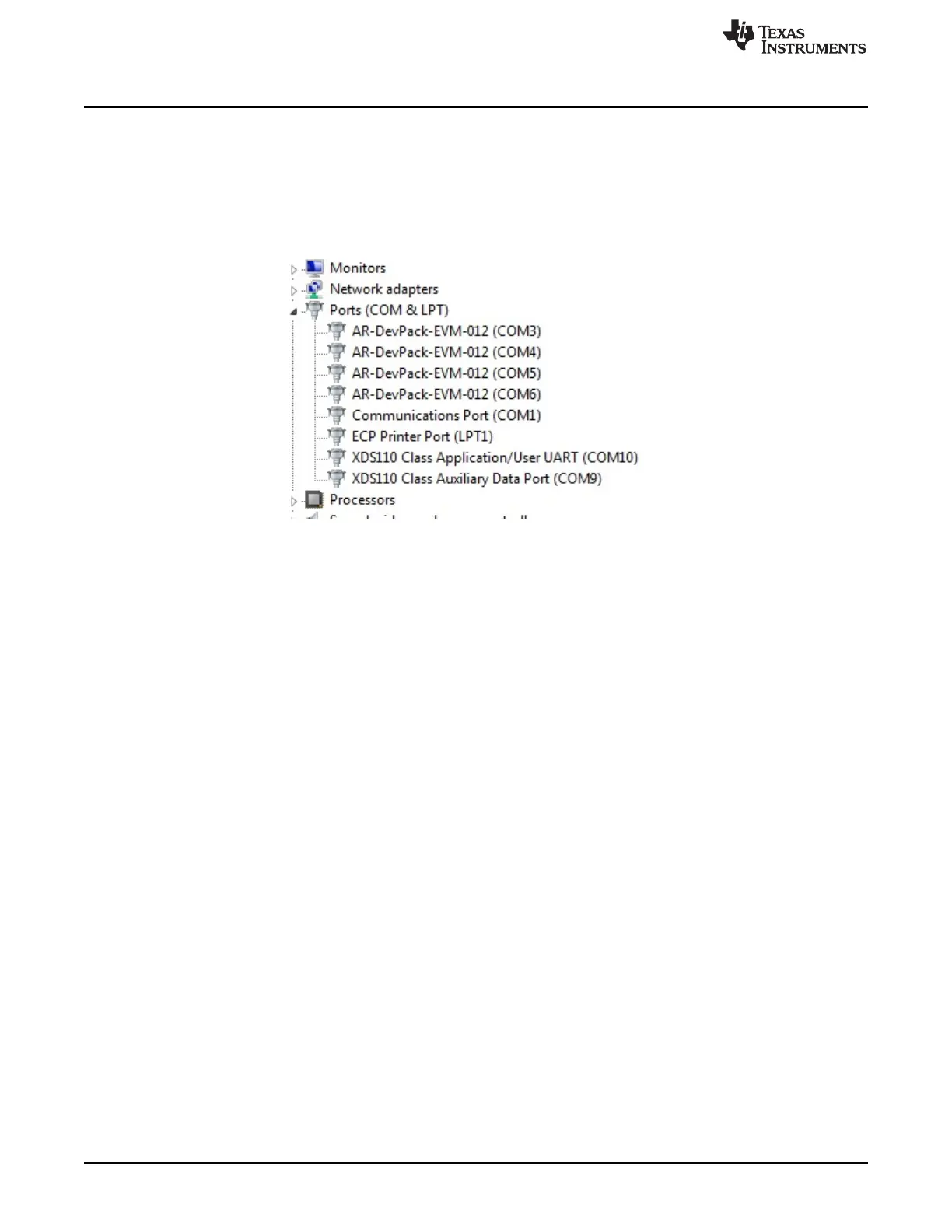
This must be done for all eight COM ports. When eight COM ports are installed, the device manager
recognizes these devices and indicates the COM port numbers, as shown in Figure 9.
Figure 9. COM Ports After the Driver Installation
2.4.2 Flashing the QSPI Flash on the Antenna Module
For the flashing, only one USB cable (XDS110 USB) must be connected to the PC; the Uniflash utility
must be used load the binary onto the antenna module. Connecting both XDS110_USB and FTDI_USB
can prevent the uniflash utility from running successfully.
2.4.3 MMWAVEICBOOST and Antenna Module Connections for Modular Testing
A compatible antenna module can be stacked on top of the MMWAVEICBOOST board using the two 60-
pin HD connectors and 12 nuts, four washers, and four M3 screws (for improving the thermal
performance). Connectors have a pin number marking shown in Figure 18 to prevent the misalignment of
the pins or reverse connection. Figure 10 shows the integration of MMWAVEICBOOST and starter kit. The
starter kit is powered by the 3.3-V supply. There is one micro USB cable to XDS110 (J11) to run the out-
of-box demo, and one micro USB cable to FTDI (J12) for initiating controls from mmWave Studio. Digital
controls from the MMWAVEICBOOST are initiated after the FTDI and XDS110 ports are detected in the
device manager shown in Figure 9. The configuration of the MMWAVEICBOOST and starter kit are based
on the analog mux settings and mux controls received from the dip switch (S1). To mux all the digital
controls to the FTDI/XDS110 connector, set the mux control switch positions to ON/OFF, as shown in
Table 1.