xWR6843ISK / IWR6843ISK-ODS REV C
www.ti.com
30
SWRU546C–October 2018–Revised April 2020
Submit Documentation Feedback
Copyright © 2018–2020, Texas Instruments Incorporated
mmWaveICBoost and Antenna Module
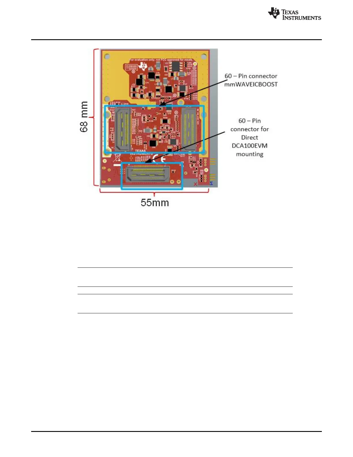
Figure 35. xWR6843ISK Rear View
3.1.2 IWR6843ISK-ODS EVM
The IWR6843ISK-ODS includes onboard-etched short range wide field of view antennas for the four
receivers and three transmitters. Figure 36 shows the PCB antennas.
NOTE: The IWR6843ISK-ODS has been tested in the 60-64GHz band across the temperature range
of -20ºC to 60ºC.
NOTE: In accordance to the EN 62311 RF exposure test, a minimum separation distance of 20
centimeters should be maintained between the user and the EVM during operation.