www.ti.com
MMWAVEICBOOST
23
SWRU546C–October 2018–Revised April 2020
Submit Documentation Feedback
Copyright © 2018–2020, Texas Instruments Incorporated
mmWaveICBoost and Antenna Module
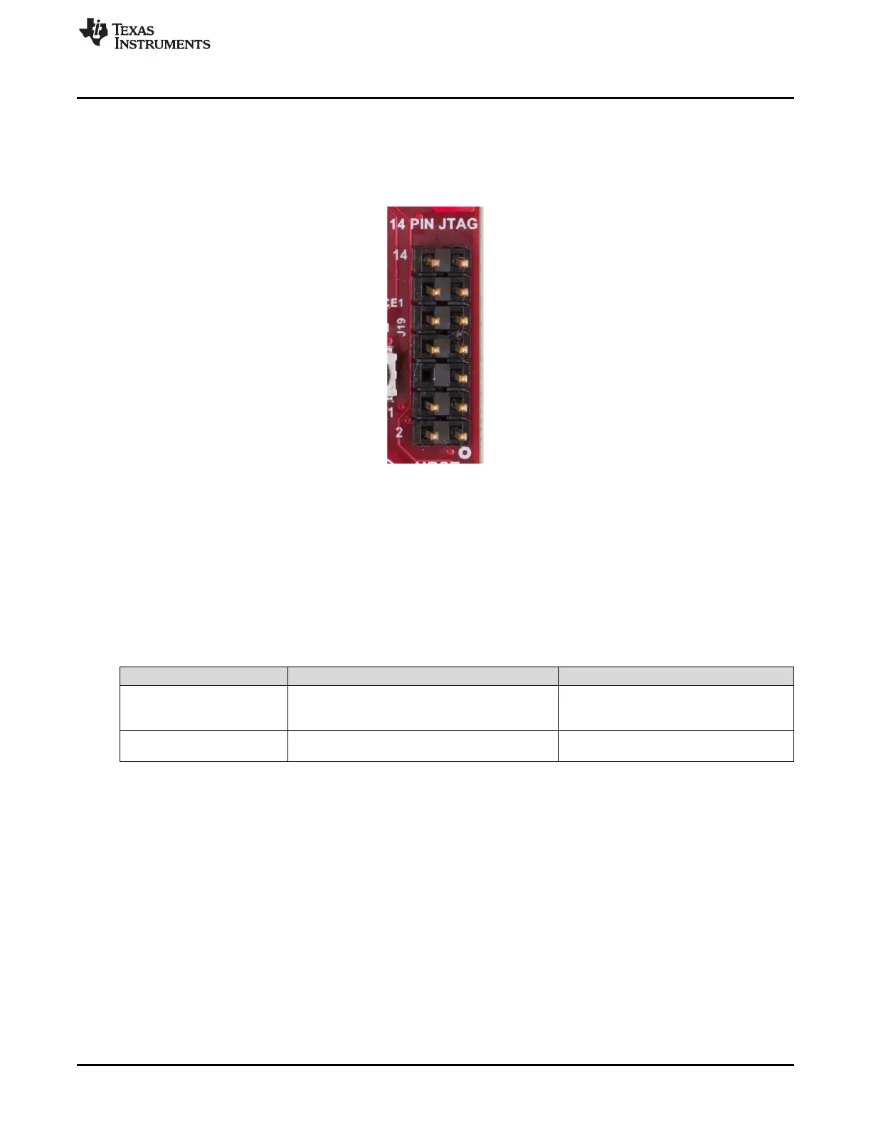
2.7.5 TI 14-Pin JTAG Connector (J19)
This connector provides a JTAG interface shown in Figure 21 for debug and development through
external XDS emulators. To use this interface, the JTAG lines to the onboard emulator (XDS110) must be
disconnected; this is done with S1 (12th position of DIP switch should be open), and the external emulator
on the MIPI 60-pin connector also must be disconnected.
Figure 21. 14-Pin JTAG Connector
2.7.6 CAN Connector (J1 and J2)
The J1 and J2 connectors shown in Table 8 provide the CAN_L and CAN_H signals from the onboard
CAND-FD transceiver (TCAN1042HGVDRQ1) and CAN transceiver (SN65HVDA540QDR) independently,
as shown in Figure 22. These signals are wired to the CAN bus after muxing with the SPI interface
signals; one of the two paths must be selected. Two CANs are selected by closing the switch S1 (1st
position of switch to be ON).
Table 8. CAN Connectivity
Pin Description Device Interface Connector on Board
SPI_CS1
SPI_CLK1
CAN2_TX
CAN2_RX
J2 pin 1 (CAN2 corresponds to Regular
CAN)
J2 pin 3
MISO_1
MOSI_1
CAN1_TX
CAN1_RX
J1 pin 1 (CAN1 corresponds to CANFD)
J1 pin 3