www.ti.com
MMWAVEICBOOST
13
SWRU546C–October 2018–Revised April 2020
Submit Documentation Feedback
Copyright © 2018–2020, Texas Instruments Incorporated
mmWaveICBoost and Antenna Module
2.4 Using the MMWAVEICBOOST With the Starter Kit
The MMWAVEICBOOST board is required with the starter kit for the following use cases:
• PC connection is enabled for communicating with the mmWave front end chip
• Connecting to mmWave Studio (mmWave Studio is a tool that provides capability to configure the
MMWAVEICBOOST front end from the PC). This tool is available online.
• The DCA1000 EVM allows users to capture the raw ADC data over the high-speed debug interface
and post process it in the PC.
• Getting DSP trace data through the MIPI 60-pin interface
• DMM interface can be used
2.4.1 PC Connection
Connectivity is provided through the micro USB connector over the onboard FTDI and XDS110 ICs. This
provides the following interfaces to the PC:
• XDS110 provides the default UART interface for application/user port and auxiliary data port
• FTDI Port A -> SPI interface for radar device control using mmWave Studio
• FTDI Port B-> I2C interface and host INTR signal
• FTDI Port C -> BSS Logger port (for internal debug only), NRST control, and Nerror signals
• FTDI Port D -> DSS Logger port, SOP line control signals, and GPIO signals
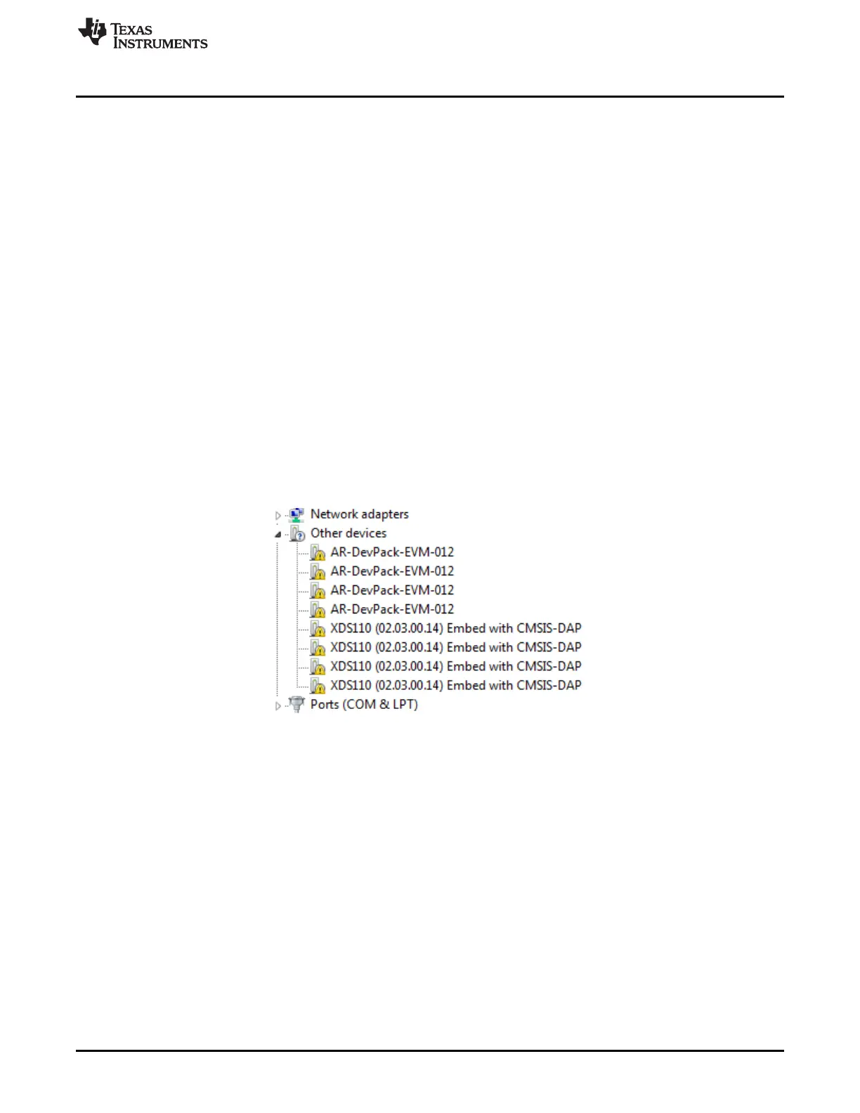
When the USB is connected for the first time to the PC, Windows® maybe not be able to recognize the
device. This is indicated in the device manager with yellow exclamation marks as shown in Figure 8.
Figure 8. Uninstalled Devices