IWR6843AOPEVM Rev F
www.ti.com
58
SWRU546C–October 2018–Revised April 2020
Submit Documentation Feedback
Copyright © 2018–2020, Texas Instruments Incorporated
mmWaveICBoost and Antenna Module
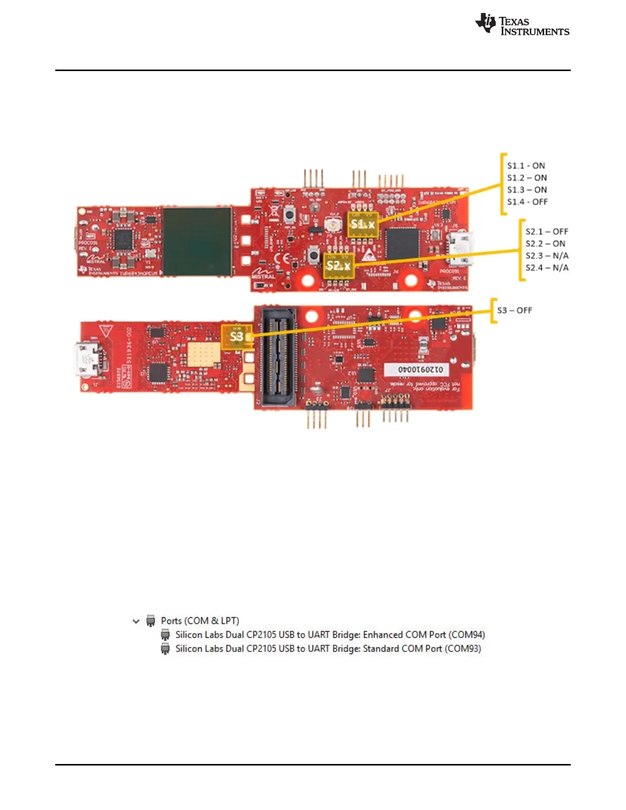
For mounted mode, the UART should be routed to the 60-pin connector. Set up the device as shown in .
When mounted as shown, the SOP mode is overridden by the MMWAVEICBOOST SOP configuration.
Figure 71. Switch Configuration for MMWAVEICBOOST Mode
4.9 PC Connection
4.9.1 Installing the Drivers
The SICP2105 drivers must be installed to access the UART port. Download and install the drivers here.
When installed correctly, the COM port should be enumerated as shown in .
Figure 72. SICP2015 COM Ports
The enhanced COM port is the application/user UART and the standard COM port is the data port.