www.ti.com
MMWAVEICBOOST
25
SWRU546C–October 2018–Revised April 2020
Submit Documentation Feedback
Copyright © 2018–2020, Texas Instruments Incorporated
mmWaveICBoost and Antenna Module
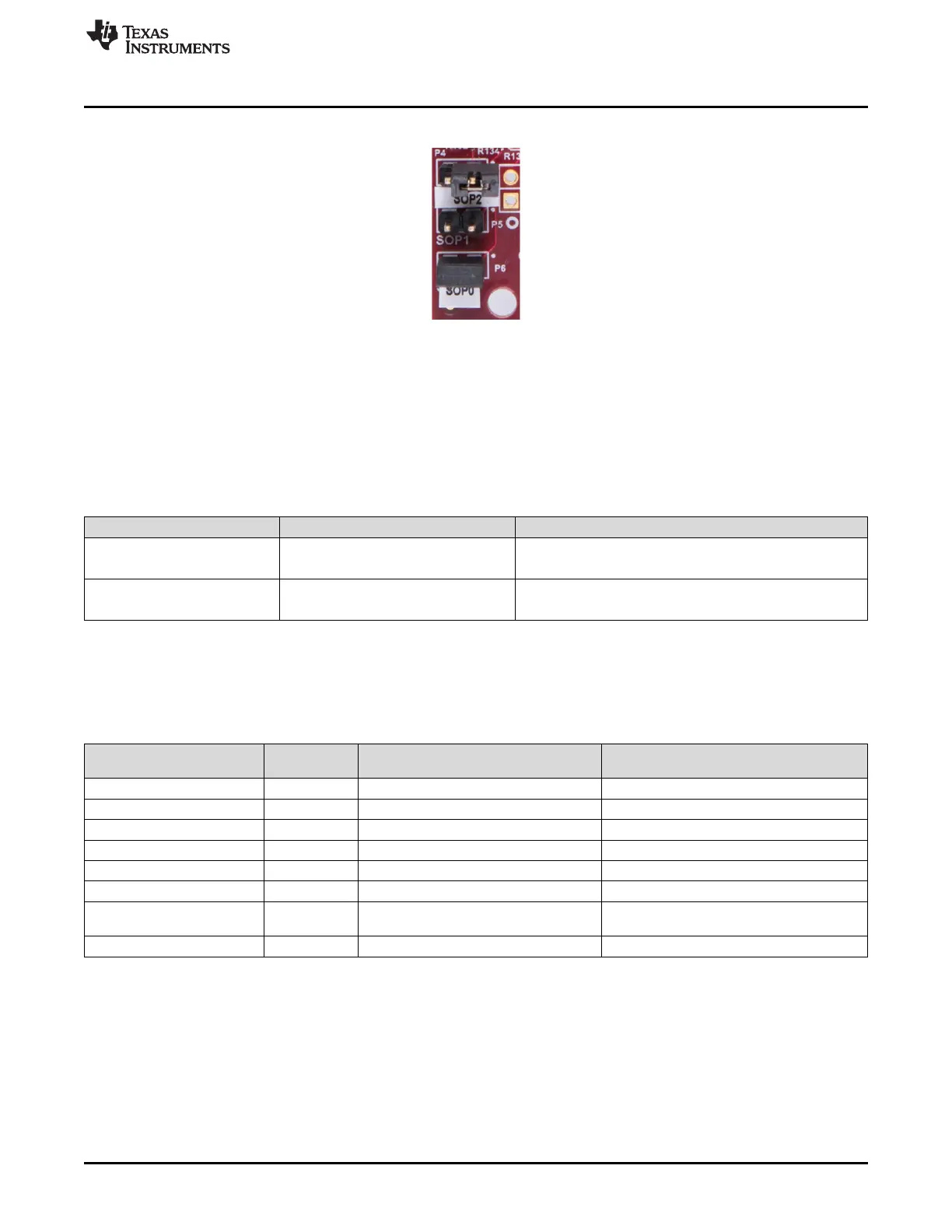
Figure 24 shows the SOP jumpers.
Figure 24. SOP Jumpers
2.8.2 I2C Connections
The board features temperature sensor for measuring onboard temperature. These are connected to the
I2C bus and can be isolated using the zero Ω provided on the hardware.
Table 10 provides the jumper settings for I2C.
Table 10. I2C Jumper Settings
Reference Designator Usage Comments
J14 I2C SCL
1-2(default) :FTDI/60 pin(J10)
2-3 : XDS110
J15 I2C SDA
1-2(default) : FTDI/60 pin(J10)
Pin 2-3 : XDS110
2.8.2.1 Default I2C Address
Table 11 provides the list of I2C devices and its address.
Table 11. I2C Devices and Addresses
Sensor Type
Reference
Designator Part Number Slave Address
Temp sensor 1 U18 TMP112AIDRLR 100 1001
Temp sensor 2 U19 TMP112AIDRLR 100 1000
Current sensor for 3.3V rail U11 INA226AIDGST 100 0010
Current sensor for 1.8V rail U21 INA226AIDGST 100 0110
Current sensor for 1.2V rail U22 INA226AIDGST 100 0111
Current sensor for 1.0V rail U23 INA226AIDGST 100 1100
Current sensor for 3.3V
(PMIC)
U20 INA226AIDGST 100 0011
PMIC U4 LP87524JRNFRQ1 110 0000