MMWAVEICBOOST
www.ti.com
26
SWRU546C–October 2018–Revised April 2020
Submit Documentation Feedback
Copyright © 2018–2020, Texas Instruments Incorporated
mmWaveICBoost and Antenna Module
PMIC(U4) rails such as 1.8 V, 1.2 V, 1.0 V, and 3.3 V are disabled by default. 3.3 V is derived from input
5-V jack, on-board micro USB connector, or from the 40-pin LaunchPad, as shown in Table 12. 3.3 V is
for the starter kits and the rest of the board to operate.
2.8.2.2 3.3-V Rail Options
Table 12. 3.3-V Rail Options
Reference Designator Description Image
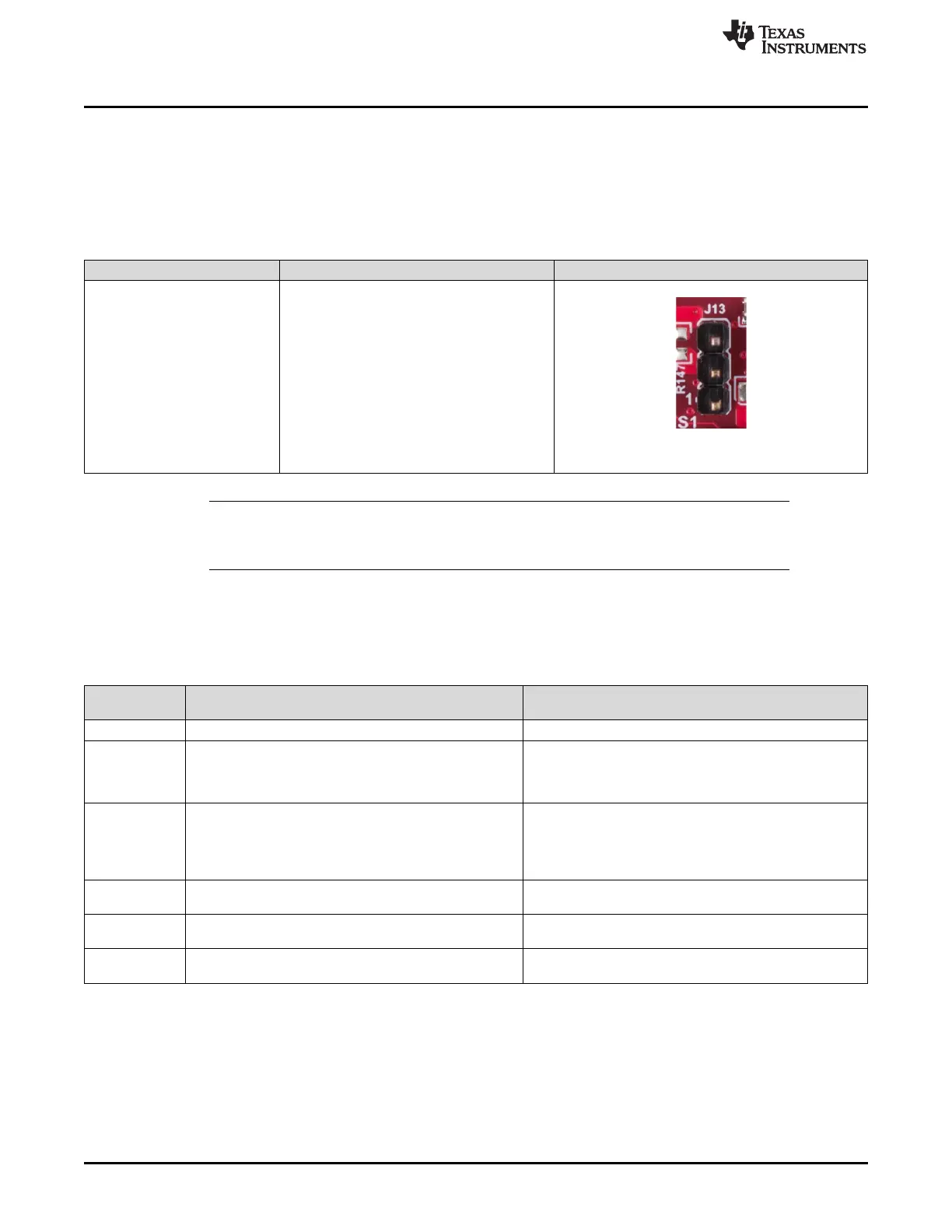
J13
Short (1-2) : 3.3 V from FTDI LDO
Short(2-3) : 3.3 V from 40-pin LP/BP connector
Open (1-2-3) : Default
Figure 25. J13 Header
NOTE: Remove the P3 jumper when using a 3.3-V rail from the 40-pin LP/BP or FTDI LDO, and
mount the R122 resistor if it is from the 40-pin LP/BP. The current rating is limited to 1A,
either from the FTDI or 40-pin LP/BP.
2.8.2.3 Miscellaneous Headers
Table 13 provides the list of miscellaneous headers and usage.
Table 13. Miscellaneous Headers
Reference
Designator Usage Comments
P1 VPP 1.7-V generation for fuse chain 1-2(default) : Closed
J27
Enables/disables the load switch (U31) of 5-V supply
generation either from > 5-V or 5-V circuitry.
(1-2) indicates >5 V
(2-3) indicates 5 V
1-2 : Open
2-3 (default) :Closed
J28
Enables/disables the load switch (U32) of 5-V supply
generation either from 5-V circuitry or 40-pin LP/BP
connector.
(1-2) indicates 20-pin LP/BP
(2-3) indicates 5 V
1-2 : Open
2-3 (default) :Closed
J16 LP/BP spare header
Onboard 10-pin header provides external user control for
configuring the LP/BP pins partially.
J18 DMM trace header 1
Onboard 16-pin header provides external user control for
JTAG trace signals.
J20 DMM trace header 2
Onboard 16-pin header provides external user control for
JTAG trace signals.