EasyManua.ls Logo

Texas Instruments mmWaveICBoost User Manual

Texas Instruments mmWaveICBoost
80 pages
To Next Page IconTo Next Page
To Previous Page IconTo Previous Page
Page #16 background image
MMWAVEICBOOST
www.ti.com
16
SWRU546COctober 2018Revised April 2020
Submit Documentation Feedback
Copyright © 2018–2020, Texas Instruments Incorporated
mmWaveICBoost and Antenna Module
2.5 Interfacing with the DCA1000EVM
The high-speed LVDS data from the radar device can be captured using the DCA1000 EVM. For more
information about the DCA1000 EVM and ordering details, see the Real Time Data Capture Adapter and
the DCA1000EVM Data Capture Card User's Guide. mmWave Studio is required for configuration. For the
installation of the tool, see the mmWave Studio User's Guide.
2.5.1 mmWave Studio Interface
To control the radar device from mmWave Studio, both the starter kit and the MMWAVEICBOOST must
be powered and connected to the PC using the micro USB cable. The UART used to download the
firmware is accessed from the XDS110 device on the MMWAVEICBOOST. The SPI interface used to
control the radar device, SOP controls, and nRST control is performed from the FTDI chip on the
MMWAVEICBOOST. For details on the usage of mmWave Studio, see the Radar Studio User's Guide that
is part of the DFP package.
2.5.2 MMWAVEICBOOST and Antenna Module Configuration
The configuration of the MMWAVEICBOOST and starter kit are the same as mentioned in Section 2.4,
except the analog mux settings and the mux controls are received from the 60-pin connector (J10) instead
of FTDI. To mux all the digital controls to the 60-pin connector, the mux control switch positions should be
set to ON/OFF, as shown in Table 1,
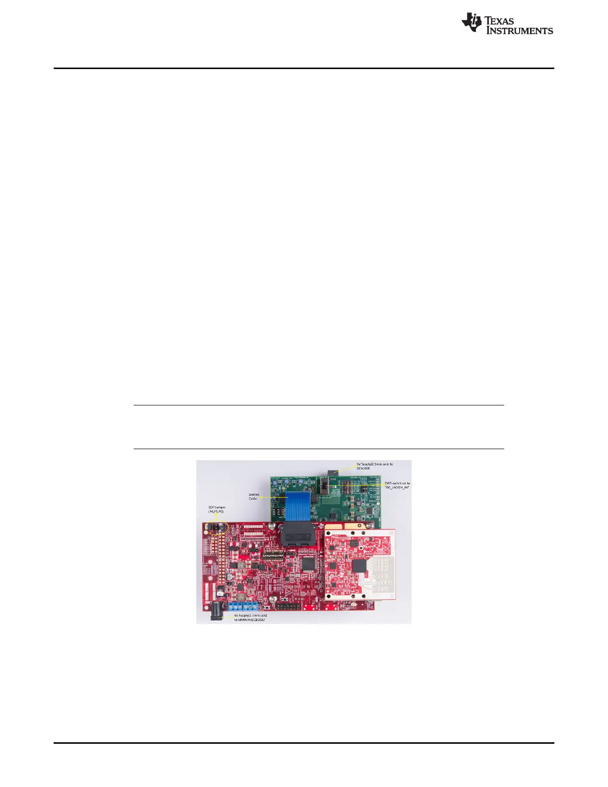
2.5.3 DCA1000 EVM Connection
The DCA1000 EVM must be powered up with a 5-V supply and the micro-USB Ethernet cable connected
to the same PC as the MMWAVEICBOOST and antenna module. A 60-pin Samtec cable (HQCD-030-
02.00-SEU-TBR-1) is used to connect the 60-pin connector (J10) on the MMWAVEICBOOST to the J3
input connector on the DCA1000 EVM. Mount the four stand offs, four washers, and pan head screws to
mate with the DCA1000EVM. For more information, see the setup shown in Figure 12.
NOTE: The Samtec cable included in the kit is the HQCD-030-02.00-SEU-TBR-1. "02.00" indicates
the length of the cable in inches; cables with longer length can be ordered by the user if
needed.
Figure 12. IWR6843ISK-MMWAVEICBOOST-DCA1000EVM Test Setup

Table of Contents

Question and Answer IconNeed help?

Do you have a question about the Texas Instruments mmWaveICBoost and is the answer not in the manual?

Texas Instruments mmWaveICBoost Specifications

General IconGeneral
BrandTexas Instruments
ModelmmWaveICBoost
CategoryMotherboard
LanguageEnglish

Summary

Getting Started

Introduction

Overview of the mmWave/CBoost and Antenna Module and its purpose.

Key Features

Highlights the main capabilities and specifications of the radar EVMs.

What's Included

Details the components provided in the EVM kit for setup and operation.

MMWAVEICBOOST

Hardware

Describes the physical components and layout of the MMWAVEICBOOST board.

Block Diagram and Features

Presents the system architecture and key functional features of the MMWAVEICBOOST.

Muxing Scheme for Multiple Sources

Explains how to configure signal routing using multiplexers for various sources.

Using the MMWAVEICBOOST With the Starter Kit

Guides on integrating and utilizing the MMWAVEICBOOST with the starter kit.

PC Connection

Details the process of connecting the EVM to a PC and driver installation.

Flashing the QSPI Flash on the Antenna Module

Instructions for updating firmware on the antenna module.

MMWAVEICBOOST and Antenna Module Connections for Modular Testing

Explains how to connect the antenna module to the MMWAVEICBOOST.

Interfacing with the DCA1000EVM

Guides on connecting the EVM to the DCA1000 for data capture.

mmWave Studio Interface

Describes controlling the radar via mmWave Studio software.

DCA1000 EVM Connection

Details the physical connection of the DCA1000EVM.

Power Connections

Information on how to power the MMWAVEICBOOST board.

Connectors

Overview of the various connectors available on the MMWAVEICBOOST.

20-Pin LaunchPad and Booster Pack Connectors (J5, J6)

Pinout details for LaunchPad and BoosterPack connectors.

60-Pin High Density (HD) Connector (J4 and J17)

Pinout details for 60-pin HD connectors.

60-Pin High Density (HD) Connector (J10)

Pinout details for the 60-pin HD connector to DCA1000.

MIPI 60-Pin Connector (J9)

Details of the MIPI 60-pin connector for JTAG.

TI 14-Pin JTAG Connector (J19)

Pinout for the 14-pin JTAG connector.

CAN Connector (J1 and J2)

Details of the CAN connectors.

Ultra-Miniature Coaxial Connector (J3)

Information on the UMC connector for clock monitoring.

Jumpers, Switches and LEDs

Configuration and status indicators on the board.

Sense on Power (SOP) Jumpers

Configuration of SOP jumpers for device modes.

I2C Connections

Details on I2C interfaces for sensors.

Default I2C Address

List of default I2C slave addresses.

3.3-V Rail Options

Options for selecting the 3.3-V power source.

Miscellaneous Headers

Description of various header connections.

Switches

Configuration settings for board switches.

LEDs

Description of LED indicators and their meanings.

xWR6843ISK / IWR6843ISK-ODS REV C

Hardware

Physical description of the xWR6843ISK and IWR6843ISK-ODS EVMs.

XWR6843ISK EVM

Specific hardware details for the xWR6843ISK EVM.

IWR6843ISK-ODS EVM

Specific hardware details for the IWR6843ISK-ODS EVM.

xWR6843ISK/IWR6843ISK-ODS Block Diagram

Functional block diagram of the xWR6843ISK/IWR6843ISK-ODS.

PCB Storage and Handling Recommendations

Guidelines for storing and handling the PCBs to prevent damage.

Power Connections

Details on powering the antenna modules.

Higher Power Applications

Information for higher power application test points.

Interfaces

Description of communication interfaces on the EVMs.

Switches, Buttons and Muxes

Configuration of switches, buttons, and multiplexers.

List of LEDs

List and description of LEDs on the board.

CANFD

Details on the CANFD interface.

I2C Connections

Information about I2C connections and devices.

xWR6843ISK Antenna

Details on the xWR6843ISK onboard antennas.

IWR6843ISK-ODS Antenna

Details on the IWR6843ISK-ODS onboard antennas.

Modular Mode

Explanation of how to use the EVM in modular mode.

DCA1000EVM Mode

Setup instructions for raw data capture with DCA1000EVM.

MMWAVEICBOOST Mode

Setup instructions for MMWAVEICBOOST mode.

IWR6843AOPEVM Rev F

Hardware

Physical description of the IWR6843AOPEVM.

Block Diagram

Functional block diagram of the IWR6843AOPEVM.

PCB Storage and Handling Recommendations

Guidelines for storing and handling the IWR6843AOPEVM.

Heat Sink and Temperature

Information on thermal management and duty cycle limits.

IWR6843AOPEVM Antenna

Details on the IWR6843AOPEVM onboard antennas.

Switch Settings

Configuration settings for the switches on the IWR6843AOPEVM.

IWR6843AOPEVM Muxing Scheme

Explains signal routing options via multiplexing.

SOP Configuration

Configuration settings for SOP modes.

Modular and MMWAVEICBOOST Mode

Usage modes for the IWR6843AOPEVM.

Modular Mode

Details on operating the EVM in modular mode.

MMWAVEICBOOST Mode

Details on operating the EVM with MMWAVEICBOOST.

PC Connection

Steps for connecting the EVM to a PC.

Installing the Drivers

Instructions for installing necessary PC drivers.

Flashing the Board

Procedure for flashing the board's firmware.

DCA1000

Guidance for DCA1000 data capture setup.

REACH Compliance

Information regarding REACH compliance and SVHC substances.

IWR6843ISK / IWR6843ISK-ODS (deprecated)

Hardware

Physical description of the deprecated IWR6843ISK/ODS EVMs.

IWR6843ISK EVM

Specific hardware details for the IWR6843ISK EVM.

IWR6843ISK-ODS EVM

Specific hardware details for the IWR6843ISK-ODS EVM.

IWR6843ISK/IWR6843ISK-ODS Block Diagram

Functional block diagram for the deprecated EVMs.

PCB Storage and Handling Recommendations

Guidelines for storing and handling the deprecated PCBs.

Power Connections

Details on powering the industrial starter kit.

Miscellaneous and LEDs

Description of miscellaneous features and status LEDs.

List of LEDs

List and description of LEDs on the board.

I2C Connections

Information about I2C connections and devices.

IWR6843ISK Antenna

Details on the IWR6843ISK onboard antennas.

IWR6843ISK-ODS Antenna

Details on the IWR6843ISK-ODS onboard antennas.

IWR6843AOPEVM (Deprecated)

Hardware

Physical description of the deprecated IWR6843AOPEVM.

Block Diagram

Functional block diagram of the deprecated IWR6843AOPEVM.

PCB Storage and Handling Recommendations

Guidelines for storing and handling the deprecated EVM.

IWR6843AOPEVM Antenna

Details on the deprecated IWR6843AOPEVM antennas.

Switch Settings

Configuration settings for switches on the deprecated EVM.

IWR6843AOPEVM Muxing Scheme

Explains signal routing options via multiplexing.

SOP Configuration

Configuration settings for SOP modes for the deprecated EVM.

Modular and MMWAVEICBOOST Mode

Usage modes for the deprecated EVM.

Modular Mode

Details on operating the deprecated EVM in modular mode.

MMWAVEICBOOST Mode

Details on operating the deprecated EVM with MMWAVEICBOOST.

PC Connection

Steps for connecting the deprecated EVM to a PC.

Installing the Drivers

Instructions for installing drivers for the deprecated EVM.

Flashing the Board

Procedure for flashing the deprecated board's firmware.

DCA1000

Guidance for DCA1000 data capture setup with deprecated EVM.

REACH Compliance

Information regarding REACH compliance and SVHC substances.

TI E2E Community

Revision History

IMPORTANT NOTICE AND DISCLAIMER

Related product manuals