MMWAVEICBOOST
www.ti.com
12
SWRU546C–October 2018–Revised April 2020
Submit Documentation Feedback
Copyright © 2018–2020, Texas Instruments Incorporated
mmWaveICBoost and Antenna Module
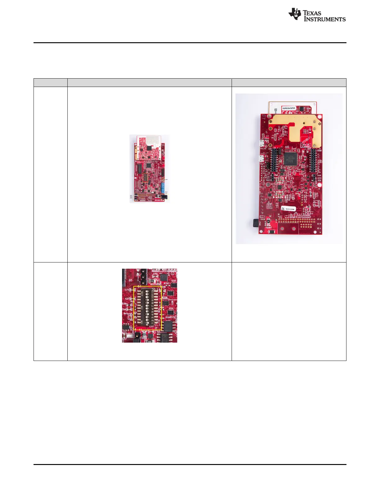
Table 2 shows the images of NRST, DIP switch settings, SOP lines, and power input locations on the
physical board.
Table 2. Mux Selection Images
Front Rear
Whole Board
Figure 5. Front
Figure 6. Rear
Zoomed IN
Figure 7. Front