www.ti.com
MMWAVEICBOOST
11
SWRU546C–October 2018–Revised April 2020
Submit Documentation Feedback
Copyright © 2018–2020, Texas Instruments Incorporated
mmWaveICBoost and Antenna Module
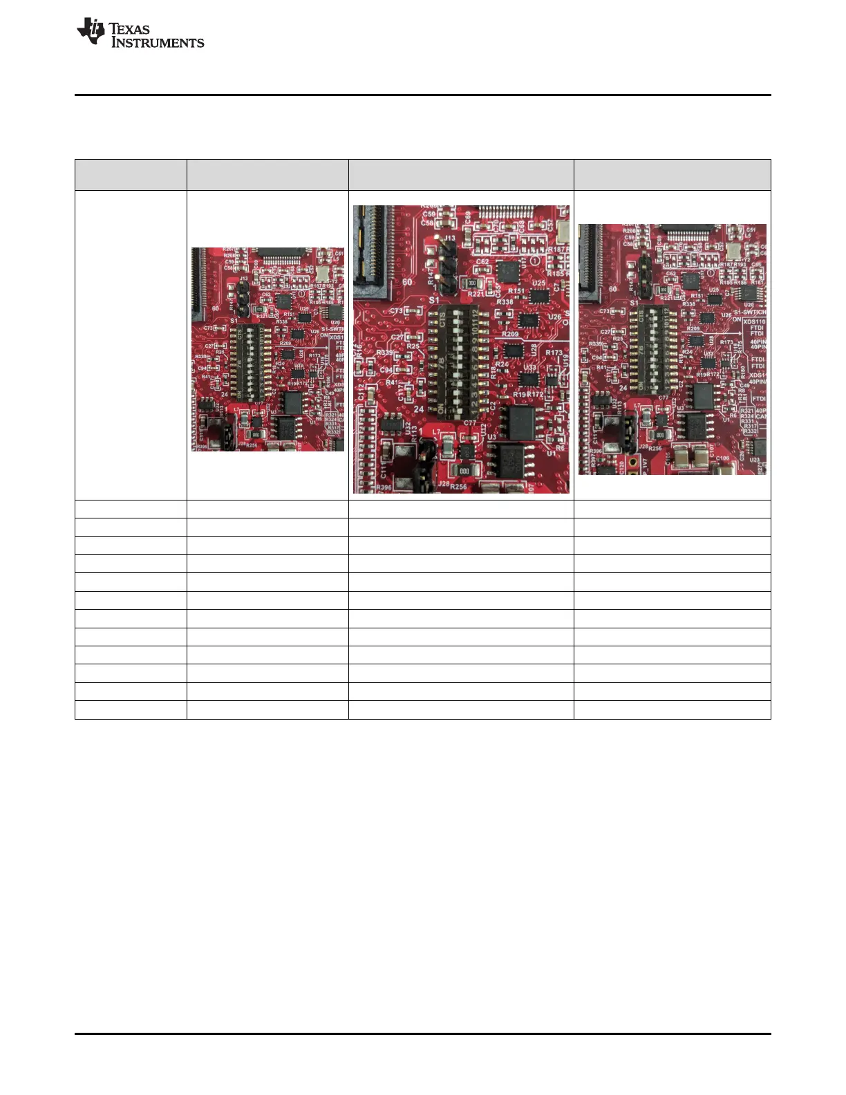
Table 1 shows the dip switch settings for multiple sources connecting to mmWave sensing device.
Table 1. Switch Settings
Reference
Designator
(Default Position) Position
for STAND ALONE Mode
(1)
Position for DCA1000 Mode Position for 40-Pin LP/BP
S1.12 ON ON ON
S1.11 ON ON OFF
S1.10 ON ON OFF
S1.9 OFF OFF ON
S1.8 OFF OFF ON
S1.7 ON OFF OFF
S1.6 ON OFF OFF
S1.5
(2)
ON ON OFF
S1.4 ON OFF ON
S1.3 ON ON OFF
S1.2 ON ON ON
S1.1 OFF OFF OFF
(1) Standalone mode means starter kit and MMWAVEICBOOST connected together.
(2) S1.5 has RS232 connections from 40 pin/FTDI/60 pin/XDS110, ON postion routes UART to XDS110 (Application/user UART
COM port).