www.ti.com
IWR6843AOPEVM Rev F
55
SWRU546C–October 2018–Revised April 2020
Submit Documentation Feedback
Copyright © 2018–2020, Texas Instruments Incorporated
mmWaveICBoost and Antenna Module
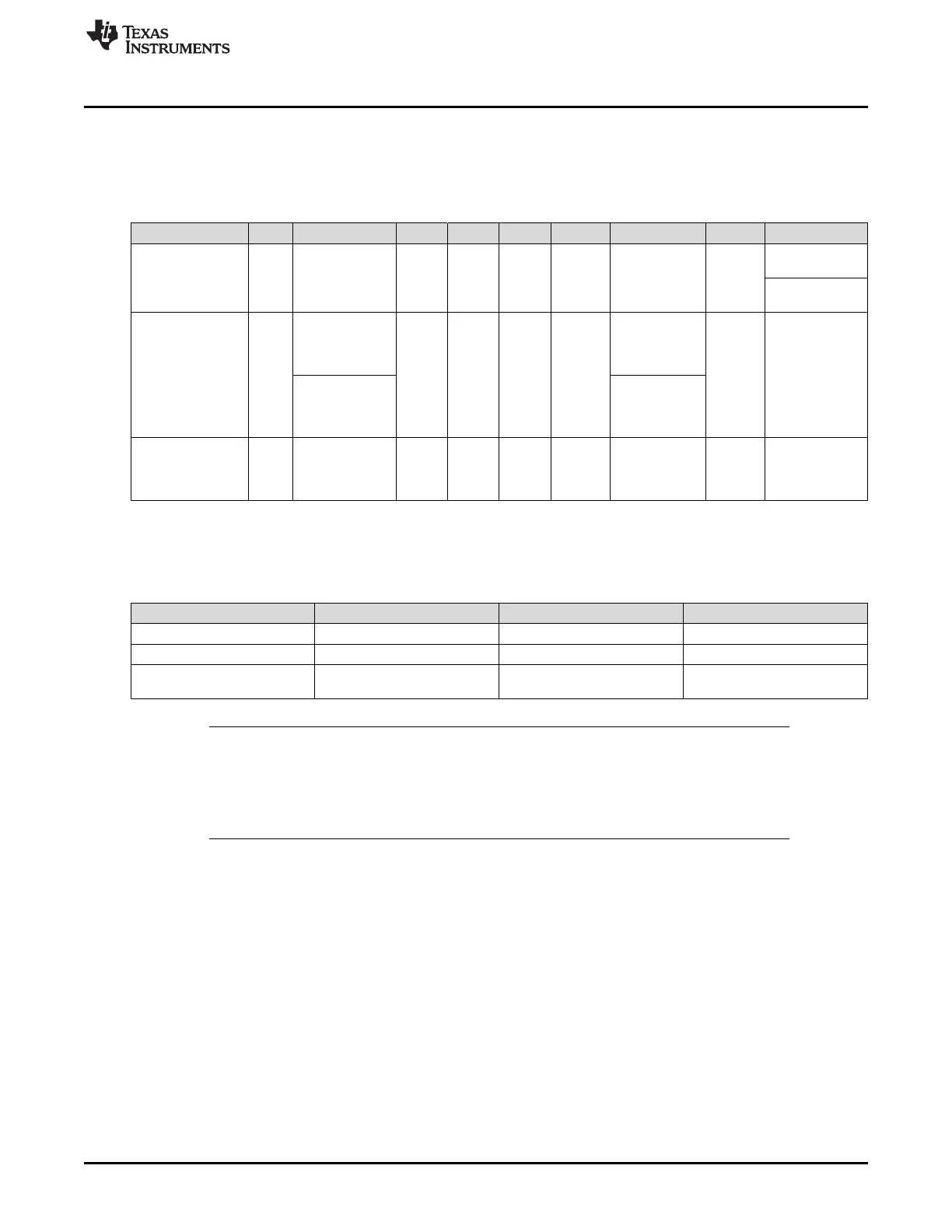
4.7 IWR6843AOPEVM Muxing Scheme
The IWR6843AOPEVM UART RX/TX can be routed to the Samtec 60-pin connector, USB to UART
(SICP2105), and bluetooth (BT) device (CC2640R2F), as detailed in Table 22
Table 22. Pin Mux Settings
Modes S1.1 S1.2 S1.3 S1.4 S2.1 S2.2 S2.3 S2.4 S3
Modular
(USB)SICP2015,
see Figure 96
OFF NA OFF OFF OFF N/A N/A N/A OFF (Functional
AOP IC Mode)
ON (Flashing
AOP IC Mode)
Modular -
(Bluetooth)CC2642
R2F, see Figure 97
ON OFF (Functional
Bluetooth Mode)
OFF OFF OFF OFF OFF
(Functional
Bluetooth
Mode)
N/A OFF
ON
(Programming
Bluetooth Mode)
ON
(Programming
Bluetooth
Mode)
MMWAVEICBOOS
T - Samtec 60 Pin
Conn, see
Figure 98
ON ON ON OFF OFF ON N/A N/A OFF
4.7.1 SOP Configuration
Table 23. SOP Configuration
SOP0(S1.3) SOP1(S1.4) SOP2(S3)
Flashing OFF OFF ON
Functional OFF OFF OFF
MMWAVEICBOOST Mode
(DCA1000, JTAG, and so forth)
ON OFF OFF
NOTE: SOP0 is pulled high when switch is on the OFF position and low when the switch is the ON
position. SOP 1 and 2 are pulled low when the switch is OFF and high when the switch is
ON.
In MMWAVEICBOOST mode, the IWR6843AOPEVM is mounted on the
MMWAVEICBOOST and the SOP mode is set by the MMWAVEICBOOST.