www.ti.com
IWR6843AOPEVM (Deprecated)
75
SWRU546C–October 2018–Revised April 2020
Submit Documentation Feedback
Copyright © 2018–2020, Texas Instruments Incorporated
mmWaveICBoost and Antenna Module
(2)
For higher power application ensure the USB J1 is connected before connecting USB J5.
6.7 Modular and MMWAVEICBOOST Mode
The IWR6843AOP can be used in modular mode or mounted on the MMWAVEICBOOST for debugging.
6.7.1 Modular Mode
When used in modular mode, the UART can either be routed to the SICP2015, which displays the data on
the mmWave visualizer, or to other devices connected to the USB interface. The UART data can also be
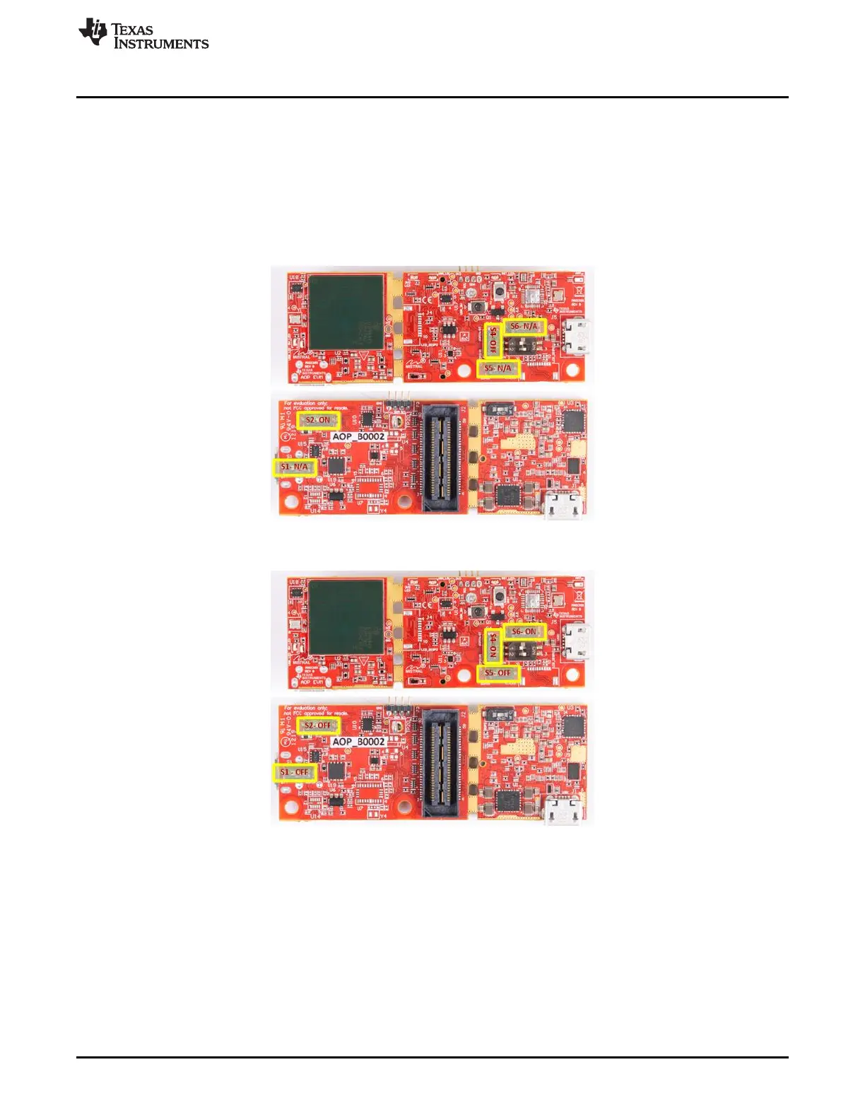
routed to the CC2640R2F, which transmits data to a wireless device through Bluetooth. Figure 96 shows
the setup for SICP2015. Figure 97 shows the setup for CC2640R2F.
(2)
Figure 96. Switch Configuration for Modular Mode
Figure 97. Switch Configuration for BT Mode