xWR6843ISK / IWR6843ISK-ODS REV C
www.ti.com
42
SWRU546C–October 2018–Revised April 2020
Submit Documentation Feedback
Copyright © 2018–2020, Texas Instruments Incorporated
mmWaveICBoost and Antenna Module
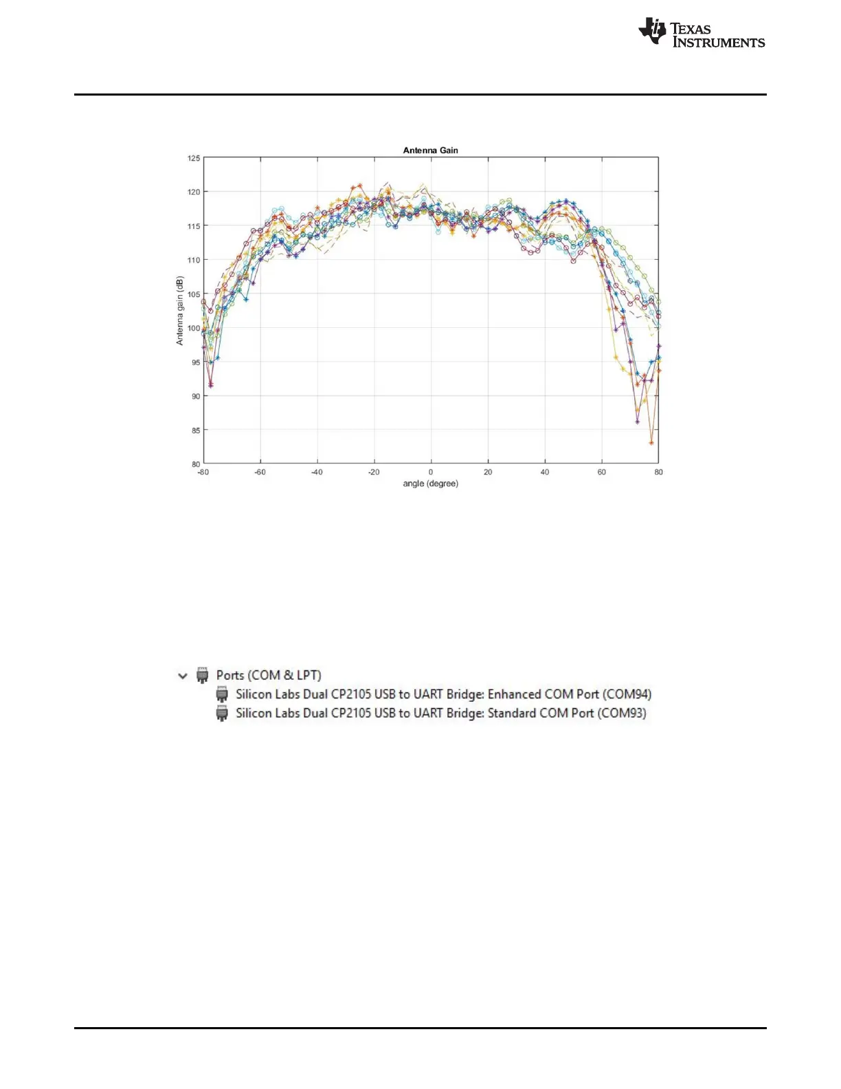
Figure 52 shows the combined Antenna Radiation pattern in the Elevation plane for all the transmitter and
receiver pairs together, TX[1-3]-RX[1-4].
Figure 52. Measured Elevation Radiation Pattern for All Tx to Rx Pairs (All 12 Virtual Antenna Pairs
Included)
3.8 Modular Mode
When used in modular mode as shown in Figure 54 the power is supply via a single USB connector, same
connector J5 is also used for data transfer through the CP2015 USB to UART emulator.
When enumerated correctly the 2 UART ports are displayed on the device manager as Virtual COM Port
similar to one shown in Figure 53
Figure 53. Virtual COM port