EasyManuals Logo

Texas Instruments mmWaveICBoost User Manual

Texas Instruments mmWaveICBoost
80 pages
To Next Page IconTo Next Page
To Previous Page IconTo Previous Page
Page #70 background imageLoading...
Page #70 background image
IWR6843AOPEVM (Deprecated)
www.ti.com
70
SWRU546COctober 2018Revised April 2020
Submit Documentation Feedback
Copyright © 2018–2020, Texas Instruments Incorporated
mmWaveICBoost and Antenna Module
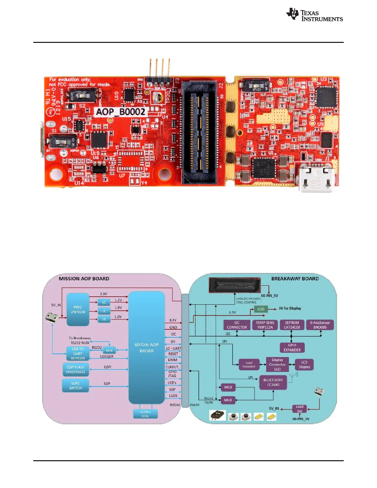
Figure 90. IWR6843AOPEVM Bottom View
6.2 Block Diagram
Figure 91 shows the functional block diagram. The mission board side contains the essential components
for the TI radar system, PMIC, SFLASH, SOP configuration, Filter, TI mmWave Radar chip, and a USB to
UART converter. The Breakaway board sections contain the 60-pin Samtec connector for interfacing with
the MMWAVEICBOOST.
Figure 91. Block Diagram of the IWR6843AOPEVM

Table of Contents

Questions and Answers:

Question and Answer IconNeed help?

Do you have a question about the Texas Instruments mmWaveICBoost and is the answer not in the manual?

Texas Instruments mmWaveICBoost Specifications

General IconGeneral
BrandTexas Instruments
ModelmmWaveICBoost
CategoryMotherboard
LanguageEnglish

Related product manuals