MMWAVEICBOOST
www.ti.com
20
SWRU546C–October 2018–Revised April 2020
Submit Documentation Feedback
Copyright © 2018–2020, Texas Instruments Incorporated
mmWaveICBoost and Antenna Module
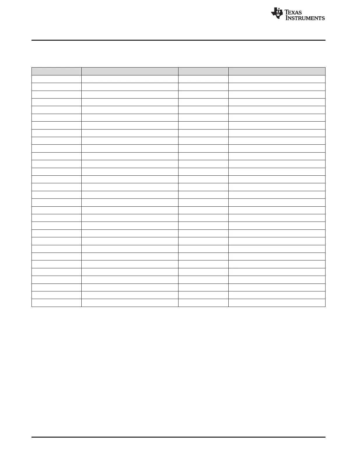
Table 6 and Table 7 list the 60-pin HD connector pinout.
Table 6. J4 Connector Pinout
Pin Number Pin Description Pin Number Pin Description
1 1V 31 DP2
2 5V 32 GND
3 1V 33 DP3
4 3.3V 34 LVDS_CLKP
5 1.2V 35 DP4
6 3.3V 36 LVDS_CLKM
7 1.2V 37 DP5
8 DMM_SYNC 38 GND
9 1.8V 39 DP6
10 DMM_CLK 40 LVDS_1P
11 JTAG_TDI 41 DP7
12 NRST 42 LVDS_1M
13 JTAG_TMS 43 BSS_LOGGER
14 PGOOD 44 GND
15 JTAG_TCK 45 OSC_CLKOUT
16 HOST_INTR1 46 LVDS_0P
17 JTAG_TDO/SOP0 47 MCU_CLKOUT
18 MSS_LOGGER 48 LVDS_0M
19 SPI_CS1 49 PMIC_CLKOUT/SOP2
20 GND 50 GND
21 SPI_CLK1 51 WARMRST
22 SYNC_IN 52 NERRIN
23 SPI_MOSI1 53 SDA
24 SYNC_OUT/SOP1 54 NERROUT
25 SPI_MISO1 55 SCL
26 GND 56 GPIO_0
27 DP0 57 RS232_RX
28 LVDS_FRCLKP 58 GPIO_1
29 DP1 59 RS232_TX
30 LVDS_FRCLKM 60 GPIO_2