PMIC
LP87524J
2 m
2 m
2 m
2 m
LC FIL
LC FIL
INA226
TEMP
SENSOR
XDS110
TO 60PIN
USB
LM536353 HEADER
JACK
HEADERLM536255
HEADER
LOADSW
2 m
INA226
HEADER
LOADSW
60 PIN HD CONNECTOR
2:1
MUX
2:1
MUX
2:1
MUX
60 PIN
CONNECTOR
DCA1000
To 60PIN
HD CONNECTOR
LVDS [6:4]
60 PIN
CONNECTOR
DCA1000
2:1
MUX
FTDI
FT4232
USB
USB XDS110
2:1 MUX
SPI 1/CAN1 & 2
TX RX
CAN1 & 2
HEADER
14PIN
JTAG
JTAG
FROM XDS110
DP [7:0]
DMM
TRACE
HEADER
DP [15:8]
60 PIN HD CONNECTOR
MIPI
60PIN
CONN
LVDS [6:4]
From
60PIN
DCA1000
GPIO [2:0], NERRIN, NERROUT, SOP [2:0], LOGGERS
SPI 1, SPI 2, NRST, INTn, RS232
SPI 1,SPI 2, NRST, INTn, RS232
SPI 1,SPI 2, NRST, INTn, RS232
GPIO [2:0], NERRIN, NERROUT,SOP [2:0], LOGGERS
3.3 V
I2C
3.3 V
1.2 V
1.8 V
1.0 V
5 V
5 V
> 5 V to 36 V
5 V
RS232
SP1
LVDS [3:0]
VCC
www.ti.com
MMWAVEICBOOST
9
SWRU546C–October 2018–Revised April 2020
Submit Documentation Feedback
Copyright © 2018–2020, Texas Instruments Incorporated
mmWaveICBoost and Antenna Module
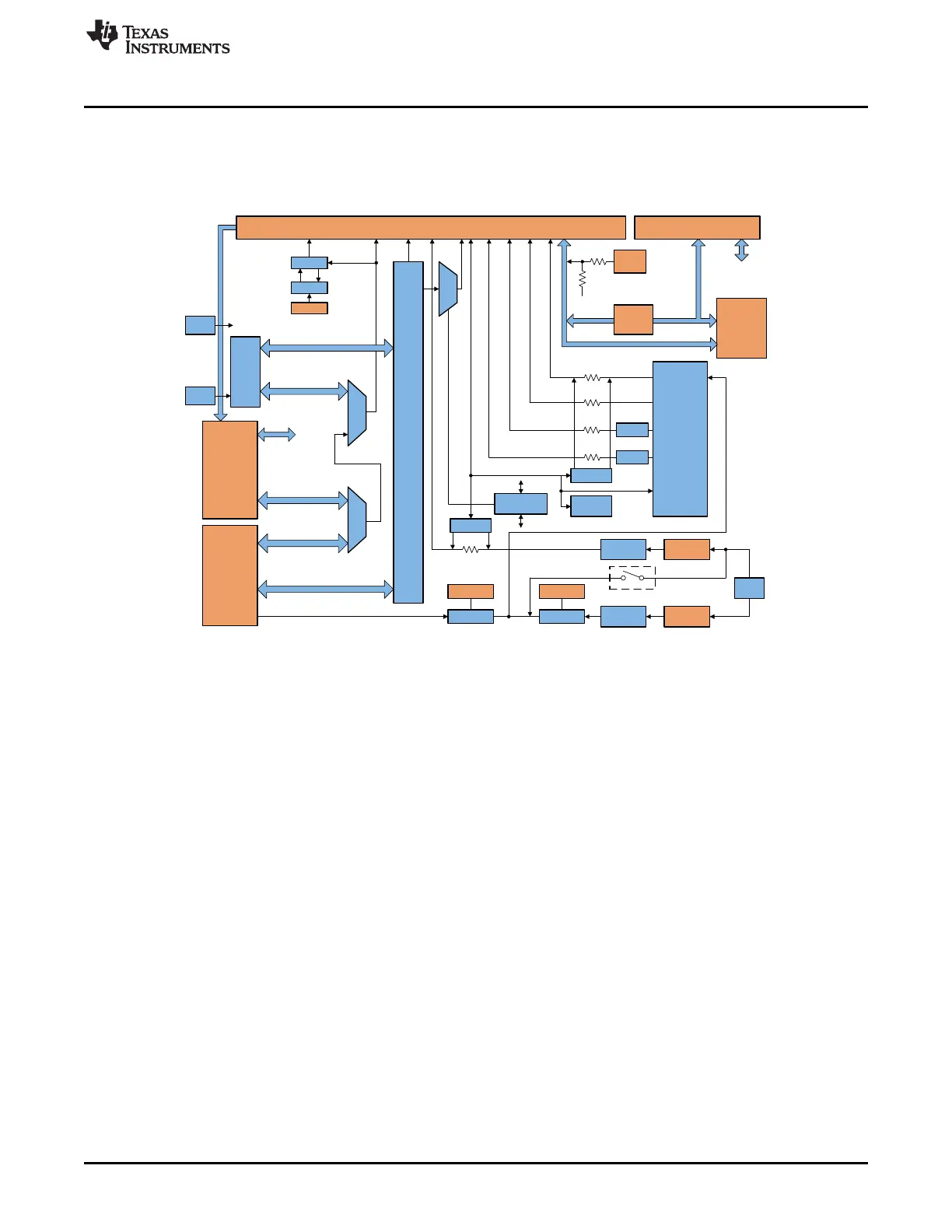
2.2 Block Diagram and Features
2.2.1 Block Diagram
Figure 3 shows the block diagram.
Figure 3. Block Diagram of MMWAVEICBOOST
2.2.2 Hardware Features
• 1 Micro USB connector for XDS110 Emulator/UART interface
• 1 Micro USB connector for FTDI interface
• One 12-pin dip switch for mux controls
• One push button and two LEDs for basic user interface
• Current sensors for all rails
• 5-V power jack to power the board
• Header for external JTAG connection