MMWAVEICBOOST
www.ti.com
18
SWRU546C–October 2018–Revised April 2020
Submit Documentation Feedback
Copyright © 2018–2020, Texas Instruments Incorporated
mmWaveICBoost and Antenna Module
2.7 Connectors
There are several types of connectors used in the MMWAVEICBOOST board, which are mentioned
below.
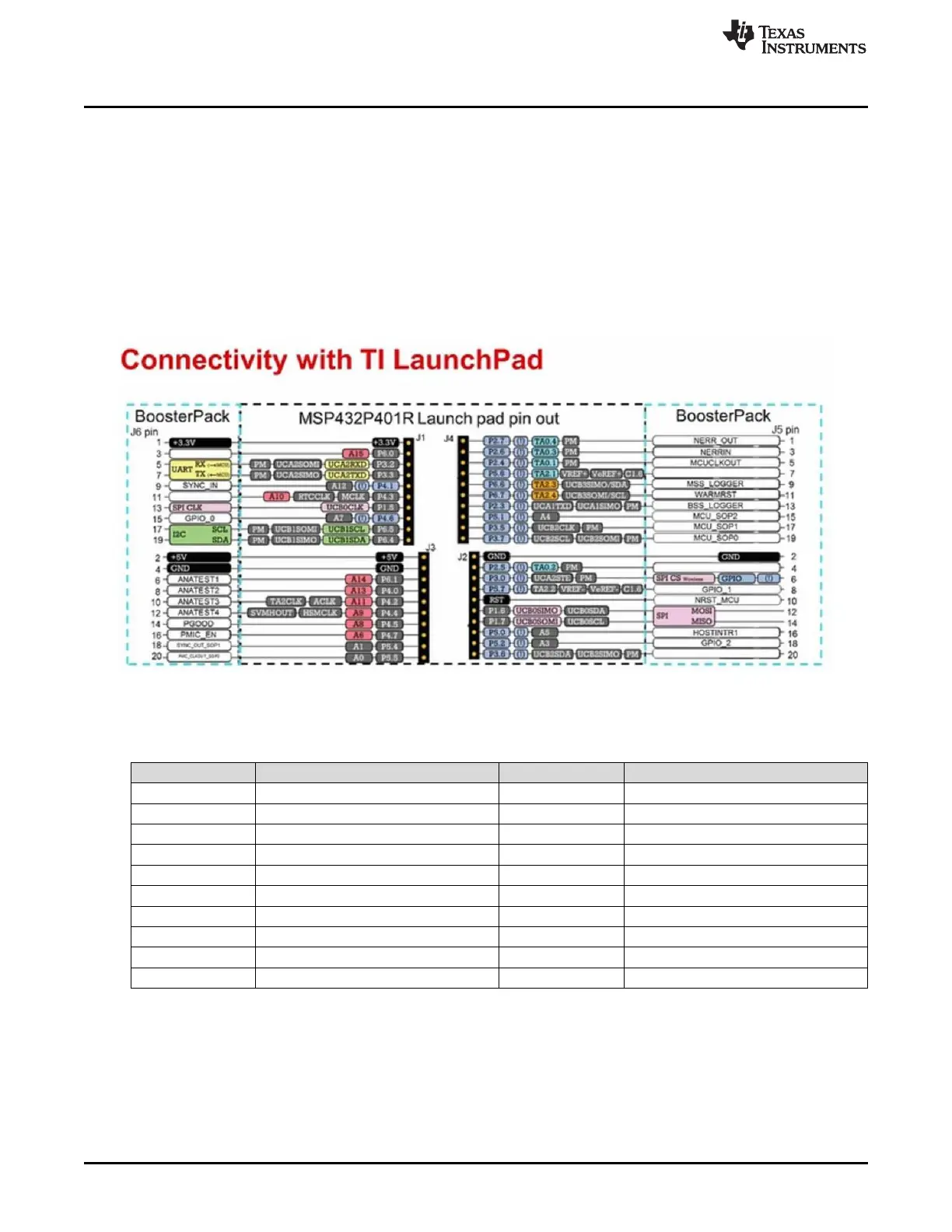
2.7.1 20-Pin LaunchPad and Booster Pack Connectors (J5, J6)
The MMWAVEICBOOST has the standard LaunchPad connectors (J5 and J6) that enable it to be directly
connected to all TI MCU LaunchPad's pinout, as shown in Figure 17. While connecting the
MMWAVEICBOOST to other LaunchPads, ensure the pin-1 orientation is correct by matching the 3V3 and
5-V signal marking on the boards. Figure 17 shows two 20-pin connectors.
Table 4 and Table 5 provide the connector pin information.
Figure 17. TI Standard LaunchPad
(1)
When running the OOB demo, the MSS_Logger pin is used to send data. This is the same pin connected to the XDS110 and
displayed through the emulator as a data COM port.
Table 4. J6 Connector Pinout
Pin Number Description Pin Number Description
1 NERROUT 2 GND
3 NERRIN 4 DSS LOGGER
5 MCUCLKOUT 6 SPI_CS
7 NC 8 GPIO1
9 MSS LOGGER (data from xWR device)
(1)
10 nRESET
11 WARMRST 12 SPI_MOSI
13 BSS LOGGER 14 SPI_MISO
15 SOP2 16 HOSTINT
17 SOP1 18 GPIO2
19 SOP0 20 NC