www.ti.com
xWR6843ISK / IWR6843ISK-ODS REV C
35
SWRU546C–October 2018–Revised April 2020
Submit Documentation Feedback
Copyright © 2018–2020, Texas Instruments Incorporated
mmWaveICBoost and Antenna Module
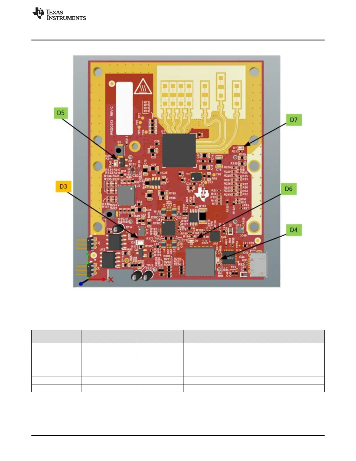
3.5.2 List of LEDs
Figure 39. LED location and color
Table 16shows the list of LEDs.
Table 16. List of LEDs
Reference
Designator Color Usage Comments
D3 Orange Power Good
This LED is used to indicate the PGOOD. If this LED is glowing
means that all voltage rails are in limits.
D4 Green USB enumeration
LED
Turns on while enumerating the USB
D5 Green Reset Toggles when reset button is depressed
D6 Green 5V indicator Indicates the application of 5V power
D7 Green GPIO 2 Connected to GPIO2, can be used when GPIO is set as output