xWR6843ISK / IWR6843ISK-ODS REV C
www.ti.com
36
SWRU546C–October 2018–Revised April 2020
Submit Documentation Feedback
Copyright © 2018–2020, Texas Instruments Incorporated
mmWaveICBoost and Antenna Module
3.5.3 CANFD
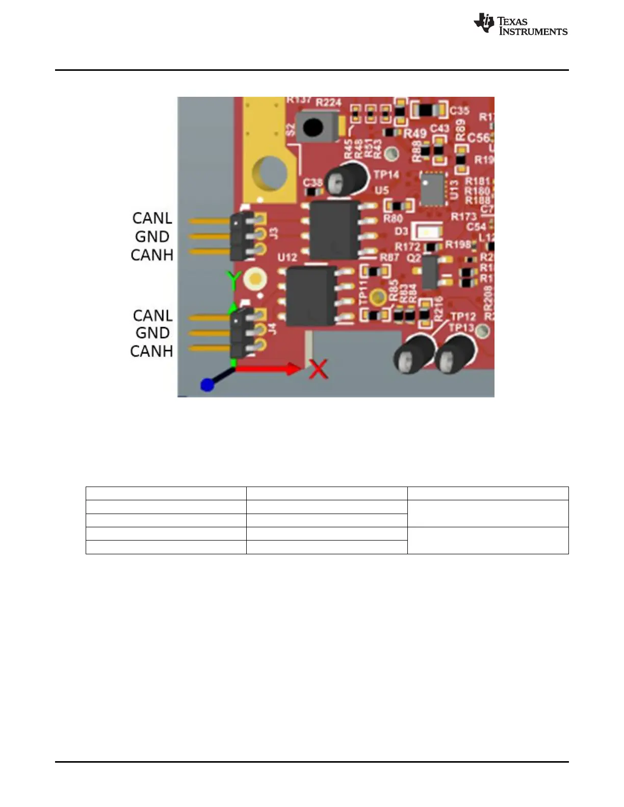
Figure 40. CAN Connector location and label
The J3 and J4 connectors shown in Figure 40 provide the CAN_L and CAN_H signals from the 2 onboard
CAND-FD transceivers (TCAN1042HGVDRQ1) These signals are wired to the CAN bus after muxing with
the SPI interface signals; one of the two paths must be selected. Two CANs are selected by closing the
switch S1.4 (1st position of switch to be ON).
Pin Description Device Interface Connector on Board
SPI_CS1 CAN2_TX J4.1 - CANL, J4.2 -GND, J4.3 - CANH
SPI_CLK1 CAN2_RX
MISO_1 CAN1_TX J3.1 - CANL, J3.2 -GND, J3.3 - CANH
MOSI_1 CAN1_RX
3.5.4 I2C Connections
The board features an EEPROM, current sensor, and temperature sensor for measuring on-board
temperature. These are connected to the I2C bus and can be isolated using the zero Ω provided on the
hardware.
3.5.4.1 EEPROM
The board features an EEPROM for storing the board specific IDs (for the identification of the starter kit
connected to the MMWAVEICBOOST).
3.5.4.2 Default I2C Address
Table 11 provides the list of I2C devices and its address.