EasyManuals Logo

Texas Instruments mmWaveICBoost User Manual

Texas Instruments mmWaveICBoost
80 pages
To Next Page IconTo Next Page
To Previous Page IconTo Previous Page
Page #45 background imageLoading...
Page #45 background image
www.ti.com
xWR6843ISK / IWR6843ISK-ODS REV C
45
SWRU546COctober 2018Revised April 2020
Submit Documentation Feedback
Copyright © 2018–2020, Texas Instruments Incorporated
mmWaveICBoost and Antenna Module
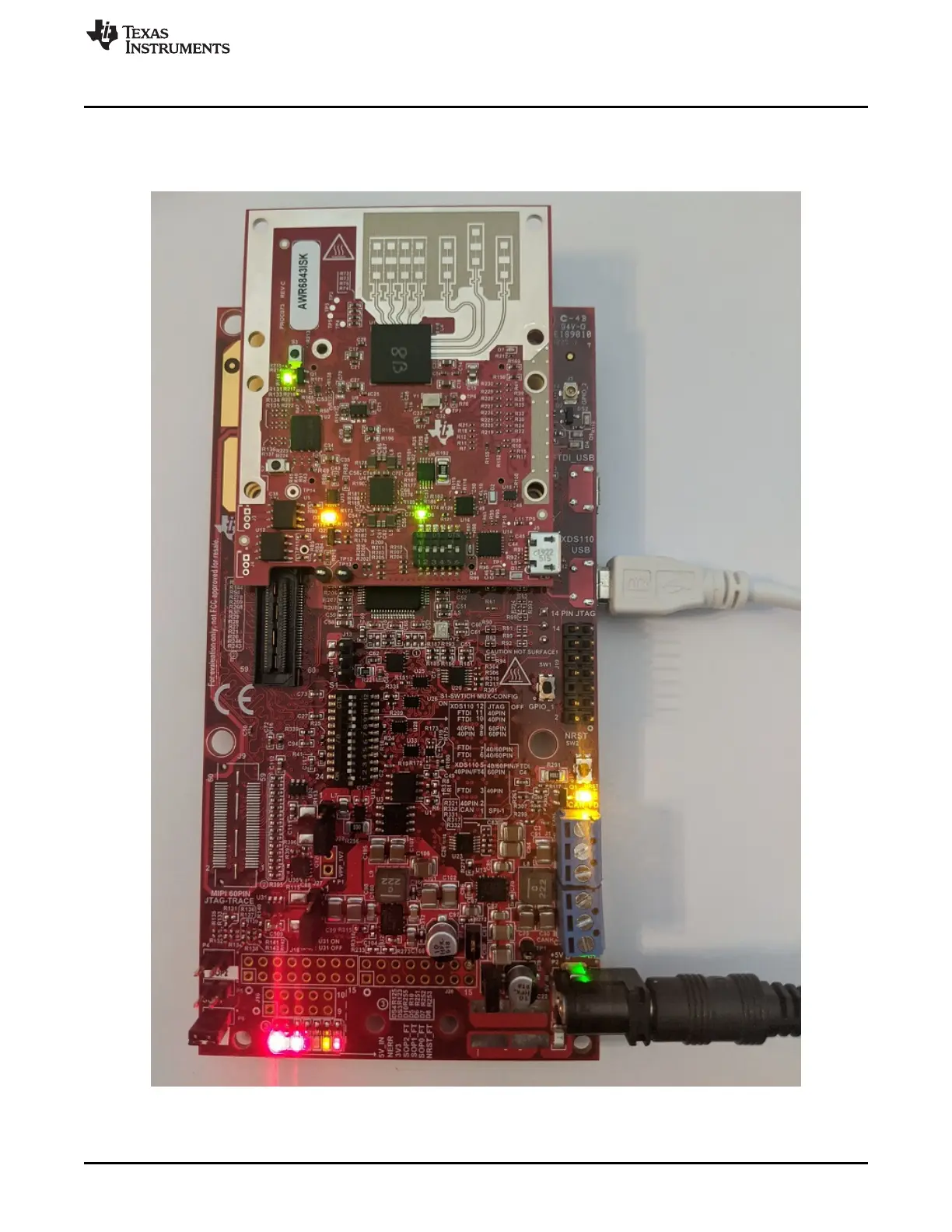
3.10 MMWAVEICBOOST Mode
In this mode the boards are setup as shown in Figure 56, UART is routed to the 60 pin connector to the
XDS110 USB. More on the mmWAVEICBOOST, setup and features it provides can be found in Section 2
Figure 56. mmWAVEICBOOST mode

Table of Contents

Questions and Answers:

Question and Answer IconNeed help?

Do you have a question about the Texas Instruments mmWaveICBoost and is the answer not in the manual?

Texas Instruments mmWaveICBoost Specifications

General IconGeneral
BrandTexas Instruments
ModelmmWaveICBoost
CategoryMotherboard
LanguageEnglish

Related product manuals