IWR6843ISK / IWR6843ISK-ODS (deprecated)
www.ti.com
64
SWRU546C–October 2018–Revised April 2020
Submit Documentation Feedback
Copyright © 2018–2020, Texas Instruments Incorporated
mmWaveICBoost and Antenna Module
5.5 Miscellaneous and LEDs
5.5.1 List of LEDs
Table 25 shows the list of LEDs.
Table 25. List of LEDs
Reference
Designator Color Usage Comments Image
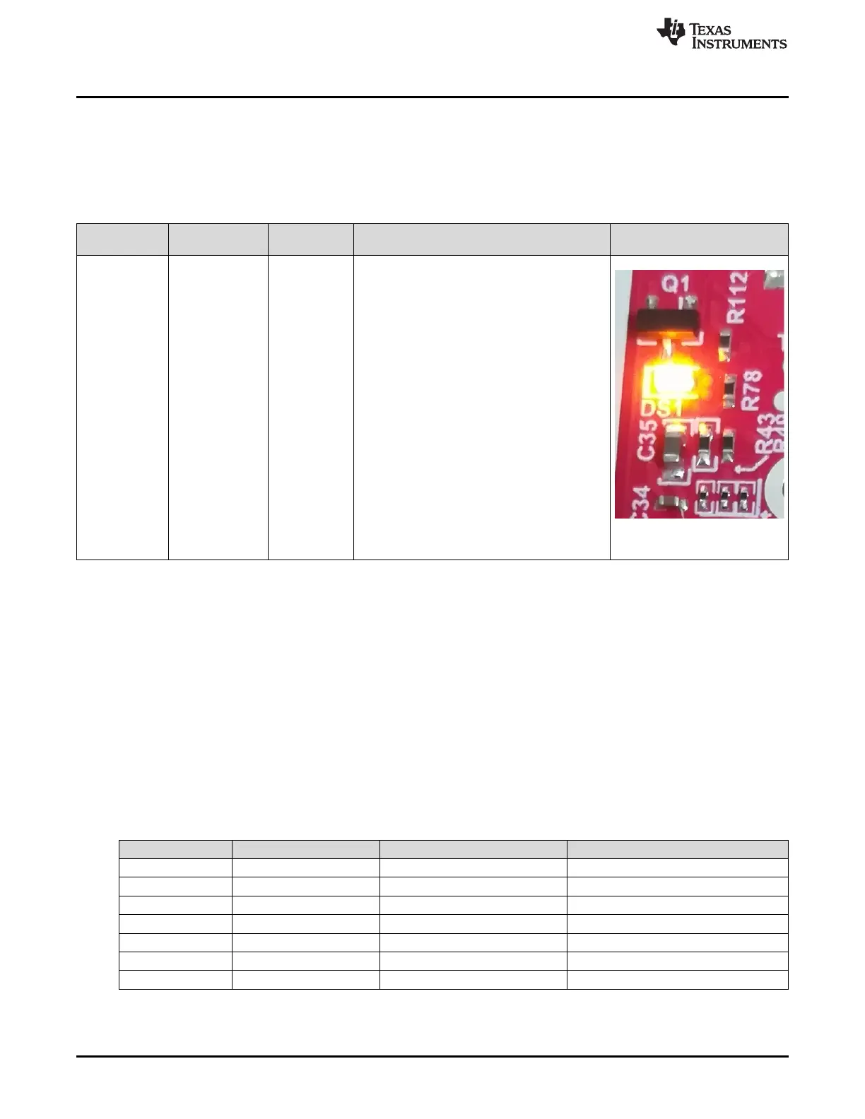
DS1 Yellow Power Good
This LED is used to indicate the PGOOD. If this
LED is glowing means that all voltage rails are in
limits.
Figure 78. PGood LED
5.5.2 I2C Connections
The board features an EEPROM, current sensor, and temperature sensor for measuring on-board
temperature. These are connected to the I2C bus and can be isolated using the zero Ω provided on the
hardware.
5.5.2.1 EEPROM
The board features an EEPROM for storing the board specific IDs (for the identification of the starter kit
connected to the MMWAVEICBOOST).
5.5.2.2 Default I2C Address
Table 26 provides the list of I2C devices and its address.
Table 26. IWR6843ISK I2C Devices and Address
Sensor Type Reference Designator Part Number Slave Address
Temperature Sensor U3 TMP112AQDRLRQ1 100 1011
EEPROM U11 CAT24C08WI-GT3 101 00XX
(1)
Current sensor1 U6 INA226AIDGST 100 0000
Current sensor2 U7 INA226AIDGST 100 0101
Current sensor3 U8 INA226AIDGST 100 0001
Current sensor4 U10 INA226AIDGST 100 0100
PMIC U4 LP87702DRHBRQ1 110 0000
(1) XX means 00,01,10,11