xWR6843ISK / IWR6843ISK-ODS REV C
www.ti.com
40
SWRU546C–October 2018–Revised April 2020
Submit Documentation Feedback
Copyright © 2018–2020, Texas Instruments Incorporated
mmWaveICBoost and Antenna Module
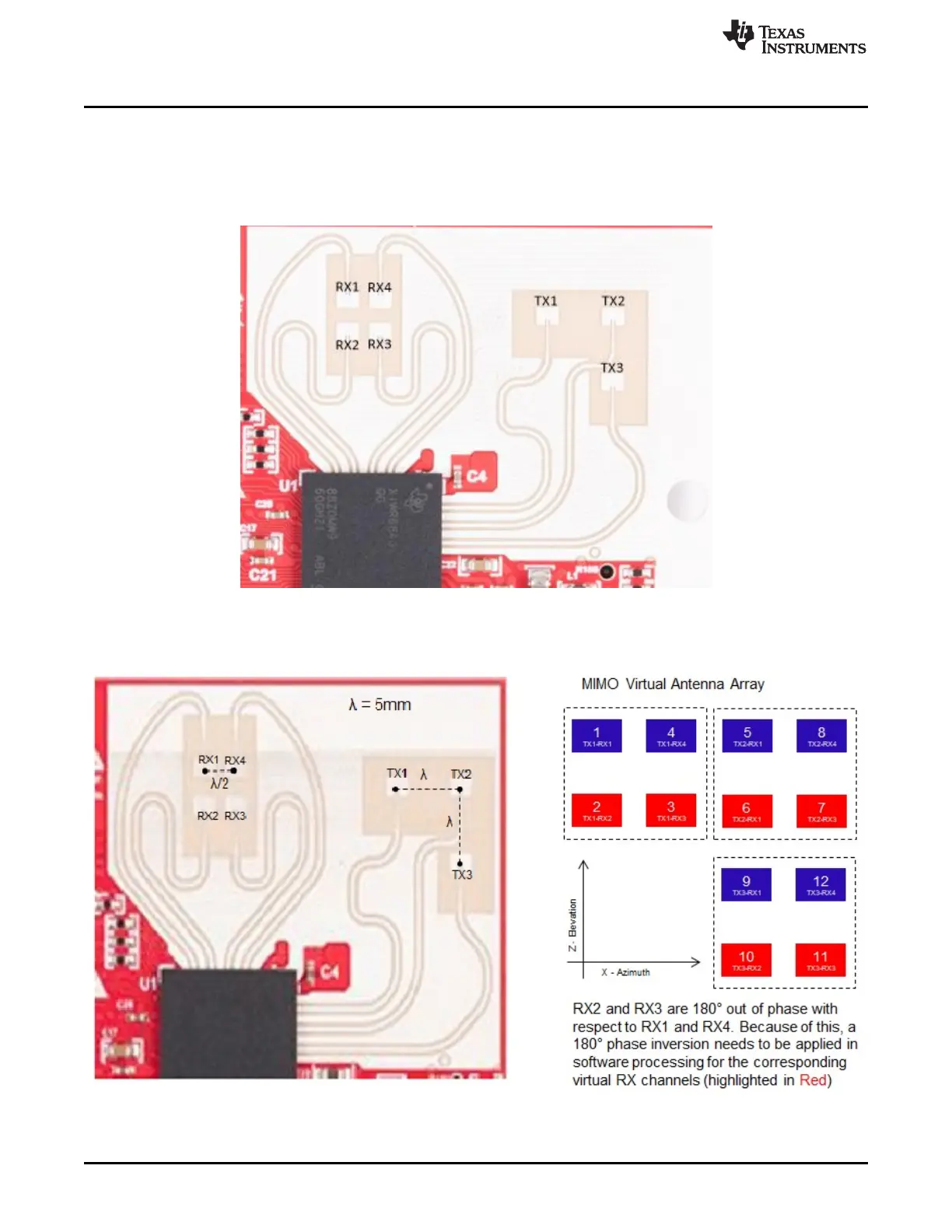
3.7 IWR6843ISK-ODS Antenna
The IWR6843ISK-ODS includes on-board-etched short range antennas (approximately 12-15 meters for
people detection) for the four receivers and three transmitters. Figure 49 shows the PCB antennas
arrangement. This provides equal angular resolution both in Azimuth and Elevation directions with the help
of 4 × 3 virtual antennas positions.
Figure 49. IWR6843ISK-ODS PCB Antenna
Figure 50. IWR6843ISK-ODS antenna placement MIMO array
Figure 51 shows combined Antenna Radiation pattern in the Azimuth plane for all the transmitter and
receiver pairs together (TX[1-3]-RX[1-4]).