www.ti.com
MMWAVEICBOOST
17
SWRU546C–October 2018–Revised April 2020
Submit Documentation Feedback
Copyright © 2018–2020, Texas Instruments Incorporated
mmWaveICBoost and Antenna Module
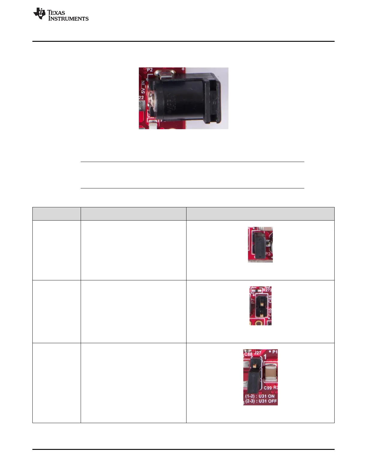
2.6 Power Connections
The board is powered by 5-V power jack (2-A current limit) shown in Figure 13.
Figure 13. Power Connector
Table 3 provides the jumper information for usage of board power input.
NOTE: TI recommends using an external power supply that complies with applicable regional safety
standards, such as UL, CSA, VDE, CCC, PSE, and more. The length of the power cable
should be < 3 m.
Table 3. Board Power
Reference
Designator Description Image
P3
Short(Default) : Input voltage is 5 V and short
R116.
Open : Input voltage is more than 5 V and
remove R116.
Figure 14. P3 Header
P7
Short : Input voltage is more than 5 V and
remove R116.
Open : Input voltage is 5 V.
Figure 15. P7 Header
J27
Short (1-2): Input voltage is more than 5 V.
Open(2-3): Input voltage is 5V(Default)
Figure 16. J27 Header