IWR6843AOPEVM Rev F
www.ti.com
48
SWRU546C–October 2018–Revised April 2020
Submit Documentation Feedback
Copyright © 2018–2020, Texas Instruments Incorporated
mmWaveICBoost and Antenna Module
Figure 58. IWR6843AOPEVM Bottom View
CAUTION
There is a possibility of damage and lose of function to the mission board when
it is split. When split, the board cannot be put back together and many features
are lost; see the Section 4.1 section for features available on the mission
board. Raw data capture, JTAG debug and other features requiring the 60 pin
SAMTEC connectors are permanently lost.
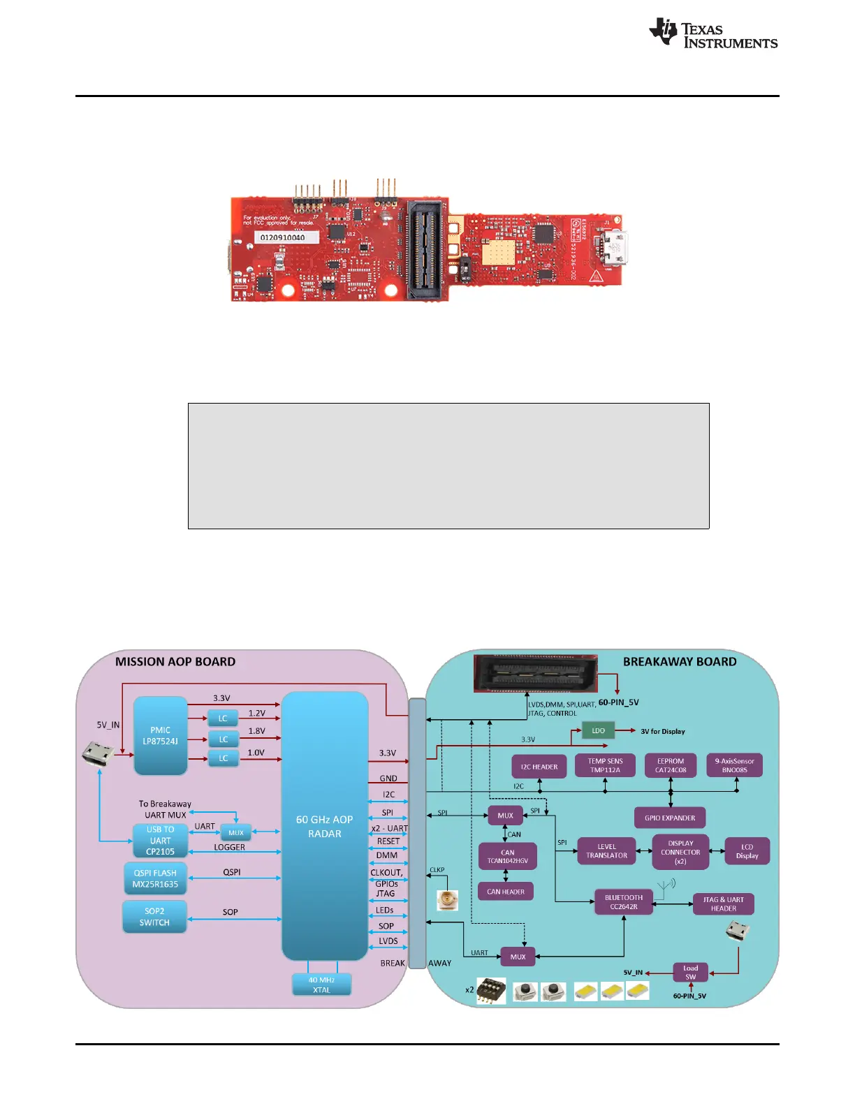
4.2 Block Diagram
Figure 59 shows the functional block diagram. The mission board side contains the essential components
for the TI radar system, PMIC, SFLASH, SOP configuration, Filter, TI mmWave Radar chip, and a USB to
UART converter. The Breakaway board sections contain the 60-pin Samtec connector for interfacing with
the MMWAVEICBOOST.
Figure 59. Block Diagram of the IWR6843AOPEVM